 JSI
JSIJainsons Industries Product Catalogue
Fire Fighting / Piping Systems
Grooved Couplings & Fittings
UL / FM ApprovedGrooved piping components including couplings, fittings and mechanical outlet products. The 2024 catalogue presents rigid/flexible coupling concepts, outlets, gaskets and pipe preparation.
CATALOGUE BROWSER
Browse the complete supplied catalogue
Use the PDF viewer for page-by-page browsing. The search box below searches the extracted catalogue text available to JSI AI.
Catalogue text
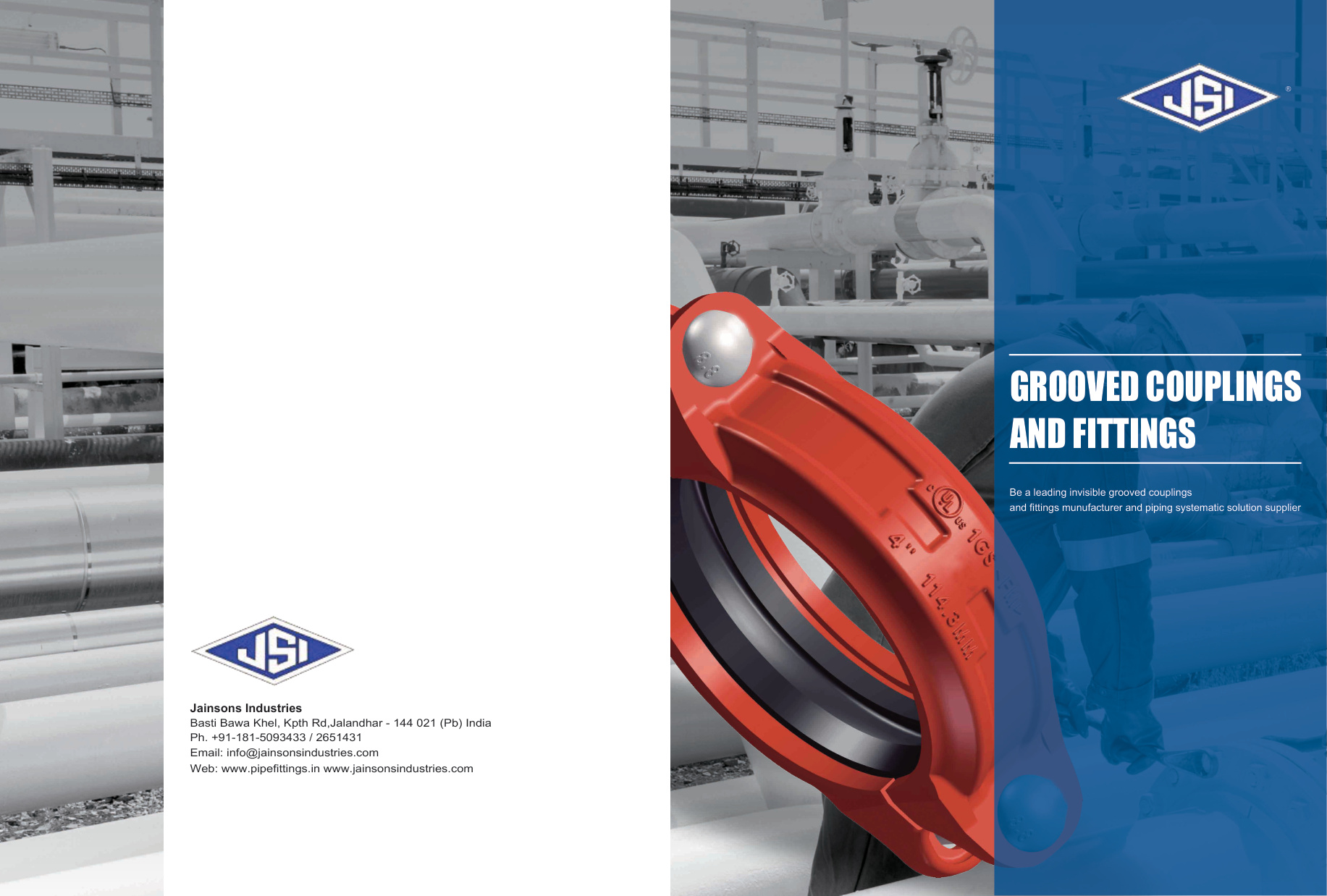
GROOVED COUPLINGS
AND FITTINGS
Be a leading invisible grooved couplings
and fittings munufacturer and piping systematic solution supplier
Jainsons Industries
Basti Bawa Khel, Kpth Rd,Jalandhar - 144 021 (Pb) India
Ph. +91-181-5093433 / 2651431
Email: info@jainsonsindustries.com
Web: www.pipefittings.in www.jainsonsindustries.com
GROOVED
COUPLING AND FITTINGS
ENTERPRISE BRIEF INTRODUCTION
Late Mr. Des Raj Jain, founder of Jainsons Industries started
production in 1971 of Malleable Pipe Fittings with production of
0.15 MT daily with a small capital of Rs. 10000/- (US$2000). As
the time passed by, the owners with their intellectual skills and
full devotion has taken the company to a recognizable standard
and presently company is producing 12 MT of fittings daily and
have plans to increase the production up to 16 MT daily within
this year. Further we are engaged in marketing of forged brass
valves namely Ball Valves, Gate Valves, Jolly Check Valves,
Foot Valves as well as UL/FM APPROVED Threaded Fittings,
Grooved Fittings and Valves all with UL FM Listins.
We strive to be a shining star in the field of Malleable
Galvanized Pipe Fittings for Natural Gas Transmission, Water
Supply & Fire Fighting. Ours is a progressive, innovative &
profitable organization in the field of the Malleable Galvanized
pipe fittings serving the needs of customers through high
quality & cost effective products & services with concern for
people & safety.
The following are the main concern in achieving our mission.
To our customer, we are committed to provide world standard
products maintaining reasonable liquidity to fulfill our financial
obligations to them.
To our employees, we are committed to provide a dynamic
developmental environment for achieving personal excellence
& growth & thereby creating a highly motivate work force with a
sense of belongingness to the organization.
To the society, we are committed to being a responsible
corporate citizen by following our obligations to the society at
large & also by maintaining high level of safety measure in our
products.
COMPANY PROFILE
1-2
The Company is producing Galvanized Malleable Cast Iron
Fittings i.e. Elbows, Tee, Socket, Union, Hex Nipple, Plug,
Caps, Cross, Reducer Elbow, Reducer Socket, Reducer Tee
etc. from size ½" to 6" for water supply, pipe joints in sanitary
and for distribution of piped Compressed Natural Gas in house
holds. Standards followed are as per IS : 1879, BS-143 & ANSI
B-16.3, EN-10242, ISO 9001 : 2008. We have been supplying
pipe fittings for last five years for piped gas to M/s. Gujarat Gas
Co. Ltd., Surat ( a British Gas Subsidiary), M/s. Mahanagar Gas
Ltd., Mumbai ( a Joint Venture of GAIL & BPCL Delhi),
Indraprastha Gas Ltd., New Delhi and GAIL India Ltd. Delhi as
well as to Delhi Metro Rail Corporation, Delhi & Adani Gas Ltd,
Ahmedabad. Moreover our Black Ductile Iron Screwed fittings
duly approved by UL/FM have been approved at following
Projects in India:
Our fittings have been approved for Common Wealth Games
Project too
COMPANY DATA
GROOVED
COUPLING AND FITTINGS
PRODUCTION EQUIPMENT
Jainsons has the most advanced production equipment.
Including Inductotherm , Denmark import automatic casting line,
domestic 416 automatic casting line, automatic Disa sand
mixer,
CNC
processing
center,
automatic
thread
processing machine, SWESS Gema automatic spray line,
automatic sealing machine and stereoscopic warehouse.
These equipments increase the capacity of production, improve
working efficiency &guaranteed the product quality.
PRODUCTION EQUIPMENTS
3-4
Jainson has own independent laboratory
& completed testing equipment. They
are rubber laboratory, metal laboratory,
chemical
laboratory,
Comprehensive
Laboratory, hydraulic testing laboratory,
piping system laboratory, etc. Those labs
and advanced equipment guaranteed for
our
products
development,
supplier
evaluation, purchasing inspection, process
inspection and final product inspection
TESTING EQUIPMENTS-RELIABLE
QUALITY ASSURANCE
GROOVED
COUPLING AND FITTINGS
TESTING EQUIPMENT
01
05
02
04
03
06
08
07
Metallography detection
Spectrum detection
The physical properties of
metal detection
Physical properties of rubber
gasket detection
Rubber gasket Synthetic high
temperature aging test
Rubber vulcanization detection
The compression stress
relaxation tests
Rubber hardness testing
01
02
03
04
05
06
07
08
|
|
|
|
|
|
|
|
5-6
APPLICATION FIELDS
APPLICATION FIELDS
CONTENT
Enterprise Brief Introduction
Production Equipments
Testing Equipments
Certiffcates Honor
Application Fields
Design Date
Products Features
Grooved Couplings
Grooved Fittings
Mechanical Outlets
Rubber Gasket
Pipe Preparation
Design Date
1-2
3-4
5-6
7-8
9-10
01-03
04-05
06-16
17-34
35-42
43-47
48-51
52-60
GROOVED
COUPLING AND FITTINGS
9-10
GROOVED
COUPLING AND FITTINGS
JSI Piping Products
This JSI General Catalog has been written for the piping system installer,
designer, specification writer and owner as a basic reference guide for
data about JSI mechanical piping methods. This catalog is organized to
provide information in the context and form most readily usable. For easy
identification of major sections of interest, see the condensed table of
contents, for a fully detailed index. For more detailed information, consult
Design Data.
JSI product data is
utilized worldwide
an d al l tech n i cal
data is shown in
both imperial (U.S.)
and metric terms.
The following chart
shows a comparison
b e t w e e n t y p i c a l
metric and IPS pipe
sizes.
After more than a decade of experience in grooved-connected pipelines, JSI
has developed multi-gauge and multi-pressure ratings of grooved products
for use with different pipe materials.
JSI standard grooved piping system products are designed for use only
with pipes and fittings that conform to the global groove standard as AWWA
C606. Piping must be prepared in accordance with the groove
specifications published by JSI and the performance data listed in this
catalog is based on the correct preparation of the piping. In particular,
installer must choose the right rubber seal material to suit applications. It
should be noted that some special applications are not recommended to
use the standard sealing material. Please refer to the "Rubber Gasket"
section of this catalog for a list of applications where rubber sealant
materials are recommended, as well as applications not recommended for
use. JSI rubber gasket must be lubricated to facilitate proper installation and
use. The seal lubricant must comply with JSI regulations or approval. Fully
lubricate the outer surface of the gasket, including the lips and tube ends,
and the housing cavity for lubrication, which will help prevent the rubber
gasket from crinkling during installation.
The technical and performance data, weights, dimensions and specifications
published in this catalog supersede all previously published data.
JSI Company maintains a policy of continual product improvement and,
therefore, reserves the right to change product specifications, designs, and
standard equipment without notice and without incurring obligation.
All data & information presented in this catalog is intended for piping design
reference in utilization of JSI products for their intended application. It is not
intended as a substitute for competent, professional assistance which is an
obvious requisite to any specific application.
Reference should always be made to design information available at no
charge on request from JSI. Good piping practices should always prevail.
Specific pressures, temperatures, external or internal loads, performance
standards and tolerances must never be exceeded. Many applications require
recognition of special conditions, code requirements and use of safety
factors. Qualified engineers must make these decisions.
While every effort has been made to ensure its accuracy, JSI Company, its
subsidiaries and affiliated companies, make no express or implied warranty of
any kind respecting the information contained in this catalog or the material
referred to herein.
Anyone making use of the information or material contained herein does so at
their own risk and assumes any and all liability resulting from such use.
Introduction
Designations of global pipe sizes
Important Information
Notice
Design
Size
Design Date
ISO
ANSI
BS
DIN
JIS
GB
Nominal Dia.
Actual O.D.
Actual O.D.
Actual O.D.
Actual O.D.
Actual O.D.
Actual O.D.
Actual O.D.
Metric
Inches
Metric
mm
Metric
mm
Metric
mm
Metric
mm
Metric
mm
Metric
mm
Metric
mm
15
1/2
21.3
21.3
21.3
21.3
21.3
21.7
21.3
20
3/4
26.9
26.9
26.7
26.9
26.9
27.2
26.9
25
1
33.4
33.7
33.4
33.7
33.7
34.0
33.7
32
11/4
42.4
42.4
42.2
42.4
42.4
42.7
42.4
40
11/2
48.3
48.3
48.3
48.3
48.3
48.3
48.3
50
2
54.0
-
-
-
-
-
54.0
57.0
-
-
-
-
-
57.0
60.3
60.3
60.3
60.3
60.3
60.5
60.3
65
21/2
73.0
-
73.0
73.0
76.1
76.1
-
76.1
76.1
76.3
76.1
80
3
88.9
88.9
88.9
88.9
88.9
89.1
88.9
90
31/2
101.6
-
101.6
101.6
101.6
101.5
102.0
100
4
108.0
-
-
-
-
-
108.0
114.3
114.3
114.3
114.3
114.3
114.3
114.3
120
41/2
127.0
-
127.0
-
-
-
127.0
125
5
133.0
-
-
-
-
-
133.0
139.7
139.7
-
139.7
139.7
139.8
139.7
141.3
-
141.3
-
-
-
141.3
150
6
152.4
-
152.4(6OD)
-
-
-
152.0
159.0
-
-
-
-
-
159.0
165.1
-
-
165.1
-
165.2
165.1
168.3
168.3
168.3
-
168.3
-
168.3
175
7
194.0
-
193.7
193.7
193.7
-
194.0
200
8
203.2
-
203.2(8OD)
-
-
-
203.0
216.3
-
-
-
-
216.3
-
219.1
219.1
219.1
219.1
219.1
-
219.1
225
9
241.8
-
-
-
-
241.8
-
245.0
-
245.0
-
-
-
245.0
250
10
254.0
-
254.0(10OD)
-
-
-
-
267.4
-
-
-
-
267.4
267.0
273.0
273.0
273.0
273.0
273.0
-
273.0
275
11
299.1
-
299.1
-
-
-
299.0
300
12
304.8
-
304.8(12OD)
-
-
-
-
318.5
-
-
-
-
318.5
318.5
323.9
323.9
323.9
323.9
323.9
-
325.0
350
14
355.6
355.6
355.6
355.6
355.6
355.6
356.0
377.0
-
-
-
-
-
377.0
400
16
406.4
406.4
406.4
406.4
406.4
406.4
406.0
426.0
-
-
-
-
-
426.0
450
18
457.2
457.2
457.2
457.2
457.2
457.2
457.0
480.0
-
-
-
-
-
480.0
500
20
508.0
508.0
508.0
508.0
508.0
508.0
508.0
530.0
-
-
-
-
-
530.0
550
22
558.8
-
558.8
559.0
558.8
558.8
560.0
600
24
609.6
610.0
609.6
610.0
609.6
609.6
610.0
630.0
-
-
-
-
-
630.0
700
28
711.2
711.0
711.2
711.0
711.2
711.2
711.0
720.0
-
-
-
-
-
720.0
800
32
812.8
813.0
812.8
813.0
812.8
812.8
813.0
900
36
914.4
914.0
914.4
914.0
914.4
914.4
914.0
1000
40
1016.0
1016.0
1016.0
1016.0
1016.0
1016.0
1016.0
1050
42
1066.8
1067.0
1066.8
-
1066.8
-
1067.0
1100
44
1117.6
1118.0
1117.6
-
1117.6
1117.6
1118.0
1200
48
1219.2
-
1219.2
-
1219.2
1219.2
1219.0
Design Date
Design Date
01/02
GROOVED
COUPLING AND FITTINGS
JSI Piping Products
Metric / Inch Conversion Chart
Products Presentation
Products Strong Point
This chart is provided
a s a g u i d e f o r
converting imperial and
metric measurements
provided within this
catalog.
Three traditional methods to connect steel pipes, namely welding, flange connection and screw
connection.
JSI grooved piping system use the grooved couplings & branch outlet fittings as the key,
supplemented by a variety of non-gasket pipefittings. This is a pipe connection revolution.
At present, JSI manufactures all kinds of grooved branch outlet fittings and non-gasket fittings.
In order to meet the needs of customers, JSI also developed extended products such as
grooved end valves, filters, etc. JSI will continue to improve and optimize so that the
company's product line can fulfill demands in civil construction, municipal and industrial fields..
JSI groove piping system is an universal, economic, safe and practical piping system
components, the installation process will not bring any pollution to the pipeline. It is an
environmentally friendly green product.
JSI groove piping system builds pipe connection on the external surface of steel pipes. The
inner diameter & interior surface of the pipe has no matter of the connection, which makes the
range of application of this product much more extended.
Compared with the traditional piping methods such as welded, flanges or threaded connection,
the grooved and mechanical outlet fittings has very significant advantages, mainly in the
following aspects:
◆ Rigid
Rigid coupling provides
enough rigidity to resist
tube twisting and bending
moment.
◆Flexibility
Flexible coupling provides
radial and axial deflection.
I t a b s o r b s e x p a n s i o n ,
contraction, deflection and
vibration.
Before attempting to install, disassemble, and adjust any JSI product, please depressurize and
drain the plumbing system. Failure to do this may result in personal injury, property damage, leaks,
and / or other potential function failure。
◆Earthquake stress
The full circumferential
engage between couplings
keys and pipe grooves
provides sufficient internal
pressure and pipe end load
capacity to withstand pipe
movement.
◆ system maintenance
S y s t e m u n i t c a n b e
disassembled without moving
the pipeline, thus facilitating
system maintenance and
modification.
◆Easy alignment
Groove system allows free
rotation of pipe and system
components prior final fixing.
Warning
Design Date
Products Features
Metric
Conversion
Conversion
Inch
Length
mm
X
0.03937
25.4
X
In
m
X
3.28084
0.3048
X
Feet(ft.)
km
X
0.621371
1.609344
X
mile
Area
mm2
X
0.00155
645.16
X
in2
m2
X
10.7639
0.0929
X
ft2
LIQUID
m3
X
264.172
0.0037854
X
usgal
m3
X
61023.7
0.0000164
X
In.3
m3
X
35.303
0.02832
X
ft3
Pressure
kpa
X
0.145
6.8948
X
PSI
kpa
X
0.01
100
X
bar
bar
X
14.5
0.068948
X
PSI
Temperature
℃
X
℃X 1.8 +32
(°F-32)/1.8
X
°F
Torque
N·m
X
0.7375
1.356
X
ft·lbf
Force
N
X
0.2248
4.4482
X
lbs.
Mass
g
X
0.035274
28.3495
X
oz.
kg
X
2.2026
0.4536
X
lbs.
Power
W
X
0.001341
745.7
X
hp
W
X
0.737562
1.35582
X
ft·lbf/s
Quantity of
Flow
L/min
X
0.2642
3.785
X
Gal. per Min. (GPM)
m3/min
X
264.2
3.7865
X
10-3 Gal. per Min.(GPM)
◆Noise and vibration
The separation between
pipe ends reduces the
transmission of noise and
vibration, provides the
entire system a significant
dampening effect
03/04
GROOVED
COUPLING AND FITTINGS
JSI Piping Products
Products Features
Grooved Couplings
JSI grooved piping system covers following categories:
●Grooved Couplings
Grooved couplings are designed as a ring self-centering connector, the inner key area of
the housing engages in the pipe grooves to provide a pipe connection. When the flexible
coupling is assembled in the pipeline, a gap is formed between the pipe ends to allow
axial displacement and lateral deflection. Rigid coupling locks the pipes directly without
deflection.
●Mechanical Outlets
The housing of branch outlet fittings has two different parts, respectively, the outlet housing
and the cover. The mechanical outlets can be composed of two outlet housing (said the
mechanical cross), or one outlet housing plus one cover(said as mechanical tee). The outlet
housing is designed as a self-positioning structure, to builds a branch outlet on the main pipe
run.
●Grooved Non-Gasket Fittings
Grooved fittings have a variety of styles, to provide flow direction turning, diameter reducing,
branching and other functions.
As the manufacturer and innovator of
grooved coupling technology, JSI offers a variety of
coupling sizes and styles for almost any piping
application.
All grooved couplings are made up of four
parts, namely housing, gasket, bolt and nut. Housing
is made of ductile iron, surface finish is orange, but
also for a variety of fluid piping system to provide
matching color scheme; standard gasket material
is EPDM, also prepared for a variety of pipeline
media rubber material. The bolt's tensile rating is
class 8.8 and the nut's rating 8.0.
JSI couplings provide pipe system with versatility not
found in other pipe connection methods. JSI rigid
and flexible couplings can be combined to allow
for thermal growth within the system. Additionally,
the use of three consecutive flexible couplings
reduces noise and vibration and eliminates
costly noise dampeners.
●Housing
Material:Ductile cast iron conforming to ASTM A-536, Grade 65-45-12.
Surface Finish:Standard:Epoxy powder coating
Optional:Galvanized (Zinc Plated、HDG), Dip painted
Surface Color:Variable colors for choice
●Rubber Gasket
Standard: EPDM.
Optional:Nitrile, Silicone, Fluoroelastomer, Neoprene
The sealing mechanism of grooved couplings and mechanical outlets is basically the same,
the main structure of the gasket has "C" shape, forming a triple seal function. The first seal
is formed by the elasticity of the gasket during the static state. After the coupling is installed,
the gasket is confined by the housing of groove coupling or the mechanical outlet, the
second seal is formed. Medium inside the pipe system press the "C" cavity after pressurizing,
it increases the adhesion between gasket lip and steel pipe surface, so as to achieve the third
reactive seal. The greater the pressure of the fluid within the pipe, The better the sealing of
the coupling.
◆ Bolt/Nut
Heat treated and electro galvanized bolts with oval neck, and heavy duty hexagon nuts.
Track head meeting the physical and chemical requirements of ASTM A-449 and physical requirements of ASTM A-183.
The material of the gasket must be chosen to follow the characteristics of the fluid medium below. The commonly used gasket are shown in the
following table:
Products Type
Products Component
Style 1X Angle-pad Rigid Coupling
DN25~DN300 1″~12″
33.4mm~323.9mm
Style 1NR Reducing Flexible Coupling
DN32~DN200 1 1/4″~8″
42.4mm~219.1mm
Style 1GS Rigid Coupling
DN25~DN300 1″~12″
33.4mm~323.9mm
Style 1N Flexible Coupling
DN25~DN300 1″~12″
33.4mm~323.9mm
Grade
Temperature
Range
Rubber
Compound
Color Code
General Service Recommendations
E
-30°F to +230°F
-34°C to +110°C
EPDM
Green
Stripe
Recommended for hot water service within the specified temperature range plus a va
riety of dilute acids, oil-free air and many chemical services. UL classified in accordance
with ANSI/NSF 61 for cold +86°F/+30°C and hot +180°F/+82°C potable water service.
NOT RECOMMENDED FOR PETROLEUM SERVICES.
T
-20°F to +180°F
-29°C to +82°C
Nitrile
Orange
Stripe
Recommended for petroleum products, hydrocarbons, air with oil vapors, vegeta
ble and mineral oils within the specified temperature range; except hot dry air over
+140°F/+60°C and water over +150°F/+66°C.
NOT RECOMMENDED FOR HOT WATER SERVICES.
O
-20°F to +300°F
-29°C to +149°C
Fluoroelastomer
Blue
Stripe
Recommended for many oxidizing acids, petroleum oils, halogenated hydrocarbons, lu
bricants, hydraulic fluids, organic liquids and air with hydrocarbons to +300°F/+149°C.
L
-30°F to +350°F
-34°C to +177°C
Silicone
Body
white
Recommended for dry heat, air without hydrocarbons to +350°F/+177°C and certain
chemical services.
V
-30°F to +180°F
-34°C to +82°C
Neoprene
Yellow
Stripe
Recommended for hot lubricating oils and certain chemicals. Good oxidation resistance.
Will not support combustion.
For specific compound and temperature compatibility, see this book Chemical Application Table
Style 321 Split Flange Adaptor
DN50~DN200 2″~8″
60.3mm~219.1mm
Style 1NH H.D. Flexible Coupling
DN25~DN300 1″~12″
33.4mm~323.9mm
05/06
GROOVED
COUPLING AND FITTINGS
JSI Piping Products
Rubber Gasket Types
Rubber Gasket Types
Style 1GS
Style 1X
Style 1N
Style 1NR
Style 321
CG1
★
★
★
RCG1
★
CG4
★
★
★
FG1
★
Grooved Couplings
Grooved Couplings
Rigid coupling connection & performance
Allow. Pipe End Sep.
The structure of the socket type rigid coupling is compact,
with the inner and outer female and male teeth, socket type,
meshing design, the use of the gap between the female and
male port socket combination of pipe and joint meshing to
achieve the rigid requirements.
Due to the improved interface structure, it is not easy to make
the gasket to produce transverse and oblique twists and turns,
the positioning of the gasket is more accurate, the abnormal
pressing and destructive pressure loss of the gaskets are
avoided, the sealing property is increased, and the overall
joint is increased service life.
The Angle-pad rigid coupling is designed to sliding rather
than vertical moving when tightening the housing. So the
pipe tightly stuck to form a rigid connection. This 60°diagonal
sliding also forces the coupling housing keys to make double
sided contact on the inside and outside edges of the groove
so that axial and radial movement of the tube cannot occur
and the effect of rigid connecting pipe is truly achieved. No
deflection after installation.
This rigid coupling allows for more accurate positioning of the
tube end forming a fixed tube end separation that should be
considered in the design and installation (see the following list
of parameters).
◆ Rigid couplings cannot be used to absorb any piping system movement.
◆ For the absorption of pipe system movement, please use flexible couplings.
Size
Allow. Pipe End Sep.
Nominal Dia.
Actual O.D.
Style 1GS
Style 1X
DN
mm
mm
mm
Inches
Inches
Inches
Inches
25
33.4
2.3
2.2
1
1.315
0.091
0.087
32
42.4
2.3
2.2
11/4
1.660
0.091
0.087
40
48.3
2.3
2.2
11/2
1.900
0.091
0.087
50
60.3
2.3
2.2
2
2.375
0.091
0.087
65
73.0
2.3
2.7
21/2
2.875
0.091
0.106
65
76.1
2.3
2.7
21/2
3.000
0.091
0.106
80
88.9
2.7
2.7
3
3.500
0.106
0.106
100
108.0
2.7
3.3
4
4.250
0.106
0.130
100
114.3
2.7
3.3
4
4.500
0.106
0.130
Size
Allow. Pipe End Sep.
Nominal Dia.
Actual O.D.
Style 1GS
Style 1X
DN
mm
mm
mm
Inches
Inches
Inches
Inches
125
133.0
2.7
3.3
5
5.250
0.106
0.130
125
139.7
2.7
3.3
5
5.500
0.106
0.130
125
141.3
2.7
3.3
5
5.563
0.106
0.130
150
159.0
2.7
3.3
6
6.250
0.106
0.130
150
165.1
2.7
3.3
6
6.500
0.106
0.130
150
168.3
2.7
3.3
6
6.625
0.106
0.130
200
219.1
4.9
4.9
8
8.625
0.193
0.193
250
273.0
4.9
4.9
10
10.750
0.193
0.193
300
323.9
4.9
4.9
12
12.750
0.193
0.193
07/08
GROOVED
COUPLING AND FITTINGS
JSI Piping Products
Flexible Coupling Systems & Performance
Allow. Pipe End Sep. & Flexibility
Using of flat joint design, flexible coupling keeps a separation between pipe ends to
achieve flexibility of pipeline. This structure ensures the strength without fully holding
the pipes, allows axial and radial displacement, suitable for deflection requirements of
the pipeline. The flexible coupling is designed to absorb the deviation of the pipe outer
diameter without affecting the joint performance
◆ All the parameters in the above table are the maximum tolerance of each flexible coupling。
◆ These values are based on standard roll grooved pipe. Figures for standard cut grooved pipe may increase.
◆ All the parameters in the above table are the maximum performance parameters. When designing and installing, the corresponding safety factor should be considered.
It is suggested that the pipe diameter of DN25 ~ DN80 should be reduced to 50% and the pipe diameter of DN100 ~ DN300 should be reduced to 75%。
Size
Allow. Pipe
End Sep.
Flexibility
Nominal Dia.
Actual O.D.
Max.
Degrees
Misalignment
DN
Inches
mm
Inches
mm
Inches
Degree(O)
mm/m
In./Ft.
25
1
33.4
1.315
2.2
0.087
2.7
47
0.57
32
11/4
42.4
1.660
2.2
0.087
2.2
38
0.46
40
11/2
48.3
1.900
2.2
0.087
2.0
34
0.42
50
2
60.3
2.375
2.2
0.087
1.9
33
0.40
65
21/2
73.0
2.875
2.4
0.094
1.8
31
0.38
65
21/2
76.1
3.000
2.4
0.094
1.8
31
0.38
80
3
88.9
3.500
2.8
0.110
1.7
29
0.36
100
4
108.0
4.250
3.3
0.130
1.6
27
0.34
100
4
114.3
4.500
3.3
0.130
1.6
27
0.34
Size
Allow. Pipe
End Sep.
Flexibility
Nominal Dia.
Actual O.D.
Max.
Degrees
Misalignment
DN
Inches
mm
Inches
mm
Inches
Degree(O)
mm/m
In./Ft.
125
5
133.0
5.250
3.6
0.142
1.3
22
0.27
125
5
139.7
5.500
3.6
0.142
1.3
22
0.27
125
5
141.3
5.563
3.6
0.142
1.3
22
0.27
150
6
159.0
6.250
3.9
0.154
1.1
19
0.23
150
6
165.1
6.500
3.9
0.154
1.1
19
0.23
150
6
168.3
6.625
3.9
0.154
1.1
19
0.23
200
8
219.1
8.625
4.9
0.193
0.85
14
0.18
250
10
273.0
10.750
4.9
0.193
0.67
11
0.14
300
12
323.9
12.750
4.9
0.193
0.58
10
0.12
Style 1GS Rigid Coupling
●Model 1GS rigid coupling,
socketed & meshing design
●Female and male port
socket design is not easy
to make the horizontal and
horizontal seal twists and
turns, the gasket is not
exposed, increasing the
sealing and improve the
overall service life of the
joint
●Enhanced body resists 4
times working pressure.
Z
Y
X
Size
Max. Work
Pressure
Max. End
Load
Allow. Pipe
End Sep.
Dimensions
Bolt/Nut
Size
Approx.
Wgt. Each
Nominal Dia.
Actual O.D.
X
Y
Z
DN
mm
KPa
N
mm
mm
mm
mm
mm
kg
Inches
Inches
PSI
Lbs.
Inches
Inches
Inches
Inches
Inches
Lbs.
25
33.4
5170
4530
2.3
54
98
44
M10X50
0.55
1
1.315
750
1020
0.091
2.126
3.858
1.732
3/8X2
1.21
32
42.4
5170
7300
2.3
63
109
44
M10X50
0.58
11/4
1.660
750
1620
0.091
2.480
4.291
1.732
3/8X2
1.28
40
48.3
5170
9470
2.3
69
115
44
M10X50
0.60
11/2
1.900
750
2130
0.091
2.717
4.528
1.732
3/8X2
1.32
50
60.3
4140
11820
2.3
83
128
45
M10X50
0.71
2
2.375
600
2660
0.091
3.268
5.039
1.772
3/8X2
1.56
65
73.0
3780
15820
2.3
97
142
46
M10X55
0.88
21/2
2.875
550
3570
0.091
3.819
5.591
1.811
3/8X21/4
1.94
65
76.1
3780
17190
2.3
100
145
46
M10X55
0.90
21/2
3.000
550
3890
0.091
3.937
5.709
1.811
3/8X21/4
1.98
80
88.9
3780
23460
2.7
113
159
47
M10X75
1.01
3
3.500
550
5290
0.106
4.449
6.260
1.850
3/8X21/4
2.22
100
108.0
3450
31610
2.7
136
192
49
M12X70
1.44
4
4.250
500
7090
0.106
5.354
7.559
1.929
1/2X23/4
3.17
100
114.3
3450
35400
2.7
142
198
49
M12X70
1.48
4
4.500
500
7950
0.106
5.591
7.795
1.929
1/2X23/4
3.26
125
133.0
3450
47930
2.7
163
224
50
M12X75
1.95
5
5.250
500
10820
0.106
6.417
8.819
1.969
1/2X3
4.30
125
139.7
3450
52880
2.7
169
230
50
M12X75
2.00
5
5.500
500
11880
0.106
6.654
9.055
1.969
1/2X3
4.41
125
141.3
3450
54100
2.7
171
232
50
M12X75
2.02
5
5.563
500
12150
0.106
6.732
9.134
1.969
1/2X3
4.45
150
159.0
3450
68500
2.7
190
249
51
M12X75
2.20
6
6.250
500
15340
0.106
7.480
9.803
2.008
1/2X3
4.85
150
165.1
3450
73860
2.7
196
254
51
M12X75
2.24
6
6.500
500
16590
0.106
7.717
10.000
2.008
1/2X3
4.93
150
168.3
3450
76750
2.7
199
257
51
M12X75
2.27
6
6.625
500
17240
0.106
7.835
10.118
2.008
1/2X3
5.00
200
219.1
2750
103680
4.9
256
328
58
M16X85
4.00
8
8.625
400
23370
0.193
10.079
12.913
2.283
5/8X33/8
8.81
250
273.0
2500
146340
4.9
311
397
59
M20X115
5.17
10
10.750
350
31770
0.193
12.244
15.630
2.323
3/4X41/2
11.39
300
323.9
2500
205990
4.9
365
451
60
M20X115
6.86
12
12.750
350
44690
0.193
14.370
17.756
2.362
3/4X41/2
15.11
◆ Housing material:Ductile iron conforming to ASTM A-536, grade 65-45-12.
◆ FM Approved & UL Listed:R.W.P. rated working pressure 300PSI(2.065MPa / 20.65bars)
◆ Housing Finish:Fusion Bonded Epoxy Coated(Optional:Hot Deep Galvanized and Others)
◆ Coupling gasket material:EPDM(Optional:Nitrile NBR,Silicone and Others)
◆ Bolts and Nuts:Heat treated and electro galvanized bolts with oval neck, and heavy duty hexagon nuts. Track head
meeting the physical and chemical requirements of ASTM A-449 and physical requirements of ASTM A-183.
◆ Size Range:DN25 through DN300 (1″ through 12″)
09/10
Grooved Couplings
Grooved Couplings
GROOVED
COUPLING AND FITTINGS
JSI Piping Products
Style 1X Rigid Coupling –Angle pad
Size
Max. Work
Pressure
Max. End
Load
Allow. Pipe
End Sep.
Dimensions
Bolt/Nut
Size
Approx.
Wgt. Each
Nominal Dia.
Actual O.D.
X
Y
Z
DN
mm
KPa
N
mm
mm
mm
mm
mm
kg
Inches
Inches
PSI
Lbs.
Inches
Inches
Inches
Inches
Inches
Lbs.
25
33.4
5170
4530
2.2
55
98
45
M10X50
0.49
1
1.315
750
1020
0.086
2.165
3.858
1.772
3/8X2
1.08
32
42.4
5170
7300
2.2
64
110
45
M10X50
0.58
11/4
1.660
750
1620
0.086
2.520
4.331
1.772
3/8X2
1.28
40
48.3
5170
9470
2.2
70
115
45
M10X50
0.62
11/2
1.900
750
2130
0.086
2.756
4.528
1.772
3/8X2
1.37
50
60.3
4140
11820
2.2
85
130
47
M10X50
0.77
2
2.375
600
2660
0.086
3.346
5.118
1.850
3/8X2
1.70
65
73.0
3780
15820
2.7
100
148
49
M10X55
0.98
21/2
2.875
550
3570
0.106
3.937
5.827
1.929
3/8X21/4
2.16
65
76.1
3780
17190
2.7
103
151
49
M10X55
1.00
21/2
3.000
550
3890
0.106
4.055
5.945
1.929
3/8X21/4
2.20
80
88.9
3780
23460
2.7
116
164
49
M10X55
1.11
3
3.500
550
5290
0.106
4.567
6.457
1.929
3/8X21/4
2.44
100
108.0
3450
31610
3.3
138
188
51
M12X70
1.48
4
4.250
500
7090
0.130
5.433
7.402
2.008
1/2X23/4
3.26
100
114.3
3450
35400
3.3
144
194
51
M12X70
1.52
4
4.500
500
7950
0.130
5.669
7.638
2.008
1/2X23/4
3.35
125
133.0
3450
47930
3.3
165
226
51
M12X75
2.07
5
5.250
500
10820
0.130
6.496
8.898
2.008
1/2X3
4.56
125
139.7
3450
52880
3.3
172
232
51
M12X75
2.12
5
5.500
500
11880
0.130
6.772
9.134
2.008
1/2X3
4.67
125
141.3
3450
54100
3.3
173
234
51
M12X75
2.14
5
5.563
500
12150
0.130
6.811
9.213
2.008
1/2X3
4.71
150
159.0
3450
68500
3.3
192
252
52
M12X75
2.42
6
6.250
500
15340
0.130
7.559
9.921
2.047
1/2X3
5.33
150
165.1
3450
73860
3.3
198
258
52
M12X75
2.48
6
6.500
500
16590
0.130
7.795
10.157
2.047
1/2X3
5.46
150
168.3
3450
76750
3.3
201
261
52
M12X75
2.53
6
6.625
500
17240
0.130
7.913
10.276
2.047
1/2X3
5.57
200
219.1
2750
103680
4.9
260
325
61
M16X85
4.49
8
8.625
400
23370
0.193
10.236
12.795
2.402
5/8X33/8
9.89
250
273.0
2500
146340
4.9
314
397
61
M20X115
5.53
10
10.750
350
31770
0.193
12.362
15.630
2.402
3/4X41/2
12.18
300
323.9
2500
205990
4.9
368
451
62
M20X115
7.22
12
12.750
350
44690
0.193
14.488
17.756
2.441
3/4X41/2
15.90
Z
Y
X
◆ Housing material:Ductile iron conforming to ASTM A-536, grade 65-45-12.
◆ FM Approved & UL Listed:R.W.P. rated working pressure 300PSI(2.065MPa / 20.65bars)
◆ Housing Finish:Fusion Bonded Epoxy Coated(Optional:Hot Deep Galvanized and Others)
◆ Coupling gasket material:EPDM(Optional:Nitrile NBR,Silicone and Others)
◆ Bolts and Nuts:Heat treated and electro galvanized bolts with oval neck, and heavy duty hexagon nuts.
Track head meeting the physical and chemical requirements of ASTM A-449 and physical requirements of
ASTM A-183.
◆ Size Range:DN25 through DN300 (1″ through 12″)
◆ Housing material:Ductile iron conforming to ASTM A-536, grade 65-45-12.
◆ FM Approved & UL Listed:R.W.P. rated working pressure 300PSI(2.065MPa / 20.65bars)
◆ Housing Finish:Fusion Bonded Epoxy Coated(Optional:Hot Deep Galvanized and Others)
◆ Coupling gasket material:EPDM(Optional:Nitrile NBR,Silicone and Others)
◆ Bolts and Nuts:Heat treated and electro galvanized bolts with oval neck, and heavy duty hexagon nuts. Track head
meeting the physical and chemical requirements of ASTM A-449 and physical requirements of ASTM A-183.
◆ Size Range:DN25 through DN300 (1″ through 12″)
●Model 1X Angle pad rigid
coupling
●This rigid coupling allows for
more accurate positioning of
the tube end, forming a fixed
tube end separation, which
should be considered in the
design and installation.
●Enhanced body resists 4 times
working pressure.
●Style 1N standard flexible
coupling provides flexible
connection by the gap
between pipe groove and
coupling key.
●Unique design allows both
axial and radial movement,
suitable for pipeline with
flexibility under intermediate
pressure.
●Enhanced body resists 4 times
working pressure.
Style 1N Flexible Coupling
Size
Max. Work
Pressure
Max. End
Load
Allow. Pipe
End Sep.
Dimensions
Bolt/Nut
Size
Approx.
Wgt. Each
Nominal Dia.
Actual O.D.
X
Y
Z
DN
mm
KPa
N
mm
mm
mm
mm
mm
kg
Inches
Inches
PSI
Lbs.
Inches
Inches
Inches
Inches
Inches
Lbs.
25
33.4
5170
4530
2.2
53
98
44
M10X50
0.55
1
1.315
750
1020
0.087
2.087
3.858
1.732
3/8X2
1.21
32
42.4
5170
7300
2.2
62
110
44
M10X50
0.58
11/4
1.660
750
1620
0.087
2.441
4.331
1.732
3/8X2
1.28
40
48.3
5170
9470
2.2
68
115
44
M10X50
0.60
11/2
1.900
750
2130
0.087
2.677
4.528
1.732
3/8X2
1.32
50
60.3
4140
11820
2.2
83
130
45
M10X50
0.71
2
2.375
600
2660
0.087
3.268
5.118
1.772
3/8X2
1.56
65
73.0
3780
15820
2.4
97
144
46
M10X55
0.90
21/2
2.875
550
3570
0.094
3.819
5.669
1.811
3/8X21/4
1.98
65
76.1
3780
17190
2.4
100
147
46
M10X55
1.00
21/2
3.000
550
3890
0.094
3.937
5.787
1.811
3/8X21/4
2.20
80
88.9
3780
23460
2.8
113
172
47
M10X55
1.11
3
3.500
550
5290
0.110
4.449
6.772
1.850
3/8X21/4
2.44
100
108.0
3450
31610
3.3
136
196
51
M12X70
1.62
4
4.250
500
7090
0.130
5.354
7.717
2.008
1/2X23/4
3.57
100
114.3
3450
35400
3.3
142
202
51
M12X70
1.66
4
4.500
500
7950
0.130
5.591
7.953
2.008
1/2X23/4
3.66
125
133.0
3450
47930
3.6
166
230
51
M16X85
2.37
5
5.250
500
10820
0.142
6.535
9.055
2.008
5/8X33/8
5.22
125
139.7
3450
52880
3.6
172
236
51
M16X85
2.42
5
5.500
500
11880
0.142
6.772
9.291
2.008
5/8X33/8
5.33
125
141.3
3450
54100
3.6
174
238
51
M16X85
2.44
5
5.563
500
12150
0.142
6.850
9.370
2.008
5/8X33/8
5.37
150
159.0
3450
68500
3.9
190
266
52
M16X85
2.72
6
6.250
500
15340
0.154
7.480
10.472
2.047
5/8X33/8
5.99
150
165.1
3450
73860
3.9
196
272
52
M16X85
2.78
6
6.500
500
16590
0.154
7.717
10.709
2.047
5/8X33/8
6.12
150
168.3
3450
76750
3.9
199
275
52
M16X85
2.83
6
6.625
500
17240
0.154
7.835
10.827
2.047
5/8X33/8
6.23
200
219.1
2750
103680
4.9
256
343
61
M20X100
5.06
8
8.625
400
23370
0.193
10.079
13.504
2.402
3/4X41/2
11.15
250
273.0
2500
146340
4.9
311
397
61
M22X135
5.91
10
10.750
350
31770
0.193
12.244
15.630
2.402
7/8X51/2
13.02
300
323.9
2500
205990
4.9
365
451
62
M22X135
7.39
12
12.750
350
44690
0.193
14.370
17.756
2.441
7/8X51/2
16.28
Y
X
Z
11/12
Grooved Couplings
Grooved Couplings
GROOVED
COUPLING AND FITTINGS
JSI Piping Products
Style 1NH Heavy Duty Flexible Coupling
Size
Max. Work
Pressure
Max. End
Load
Allow. Pipe
End Sep.
Dimensions
Bolt/Nut
Size
Approx.
Wgt. Each
Nominal Dia.
Actual O.D.
X
Y
Z
DN
mm
KPa
N
mm
mm
mm
mm
mm
kg
Inches
Inches
PSI
Lbs.
Inches
Inches
Inches
Inches
Inches
Lbs.
25
33.4
10350
9068
2.2
57
101
44
M10X50
0.73
1
1.315
1500
2037
0.087
2.244
3.976
1.732
3/8X21/4
1.61
32
42.4
860
1214
2.2
66
113
45
M12X60
0.91
11/4
1.660
1250
2705
0.087
2.598
4.449
1.772
1/2X23/8
2.00
40
48.3
860
1576
2.2
72
121
45
M12X60
0.97
11/2
1.900
1250
3544
0.087
2.835
4.764
1.772
1/2X23/8
2.14
50
60.3
860
2456
2.2
87
138
47
M12X60
1.20
2
2.375
1250
5538
0.087
3.425
5.433
1.850
1/2X23/8
2.64
65
73.0
6900
28879
2.4
101
152
49
M12X75
1.52
21/2
2.875
1000
6492
0.094
3.976
5.984
1.929
1/2X3
3.35
65
76.1
6900
31384
2.4
104
155
49
M12X75
1.54
21/2
3.000
1000
7069
0.094
4.094
6.102
1.929
1/2X3
3.39
80
88.9
6900
42830
2.8
118
170
49
M12X75
1.71
3
3.500
1000
9621
0.110
4.646
6.693
1.929
1/2X3
3.77
100
108.0
6900
63210
3.3
142
206
51
M16X85
2.60
4
4.250
1000
14186
0.130
5.591
8.110
2.008
5/8X33/8
5.73
100
114.3
6900
70800
3.3
148
212
51
M16X85
2.67
4
4.500
1000
15904
0.130
5.827
8.346
2.008
5/8X33/8
5.88
125
133.0
6900
95861
3.6
169
243
51
M20X115
3.58
5
5.250
1000
21648
0.142
6.654
9.567
2.008
3/4X41/2
7.89
125
139.7
6900
105763
3.6
176
249
51
M20X115
3.65
5
5.500
1000
23758
0.142
6.929
9.803
2.008
3/4X41/2
8.04
125
141.3
6900
108199
3.6
177
251
51
M20X115
3.67
5
5.563
1000
24306
0.142
6.969
9.882
2.008
3/4X41/2
8.08
150
159.0
6900
137004
3.9
197
271
51
M20X115
4.05
6
6.250
1000
30680
0.154
7.756
10.669
2.008
3/4X41/2
8.92
150
165.1
6900
147718
3.9
203
277
51
M20X115
4.13
6
6.500
1000
33183
0.154
7.992
10.906
2.008
3/4X41/2
9.10
150
168.3
6900
153500
3.9
206
279
51
M20X115
4.15
6
6.625
1000
34472
0.154
8.110
10.984
2.008
3/4X41/2
9.14
200
219.1
5500
207366
4.9
267
357
63
M22X135
8.35
8
8.625
800
46741
0.193
10.512
14.055
2.480
7/8X51/2
18.39
250
273.0
5500
321943
4.9
320
410
65
M24X135
10.70
10
10.750
800
72610
0.193
12.598
16.142
2.559
1X51/2
23.57
300
323.9
5500
453185
4.9
370
460
65
M24X135
12.30
12
12.750
800
102141
0.193
14.567
18.110
2.559
1X51/2
27.09
Y
X
Z
◆ Housing material:Ductile iron conforming to ASTM A-536, grade 65-45-12.
◆ FM Approved & UL Listed:R.W.P. rated working pressure 300PSI(2.065MPa / 20.65bars)
◆ Housing Finish:Fusion Bonded Epoxy Coated(Optional:Hot Deep Galvanized and Others)
◆ Coupling gasket material:EPDM(Optional:Nitrile NBR,Silicone and Others)
◆ Bolts and Nuts:Heat treated and electro galvanized bolts with oval neck, and heavy duty hexagon nuts. Track head
meeting the physical and chemical requirements of ASTM A-449 and physical requirements of ASTM A-183.
◆ Size Range:DN40 X DN32 through DN200 X DN150 (11/2″ X 11/4″ through 8″X6″)
●Style 1NH heavy duty flexible
coupling provides flexible
connection by the gap
between pipe groove and
coupling key.
●Unique design allows both
axial and radial movement,
suitable for pipeline with
flexibility under intermediate
pressure.
●Enhanced body resists 4 times
working pressure.
●Model 1NR is a reducing
flexible coupling. Two ends
can connect to different
diameter of steel pipe. The
middle of the coupling with a
steel plate to avoid telescope
by vertical installation.
●The structure ensures lower
cost and faster installation
u n d e r t h e p r e m i s e o f
ensuring the strength.
●Enhanced body resists 4 times
working pressure.
Style 1NR Reducing Flexible Coupling
Size
Max. Work
Pressure
Max. End
Load
Allow. Pipe
End Sep.
Dimensions
Bolt/Nut
Size
Approx.
Wgt. Each
Run Pipe
X
Branch Pipe
X
Y
Z
mm
X
mm
KPa
N
mm
mm
mm
mm
mm
kg
Inches
X
Inches
PSI
Lbs.
Inches
Inches
Inches
Inches
Inches
Lbs.
48.3
X
42.4
3800
5365
2.4
64
129
47
M10X50
0.66
11/2
11/4
550
1190
0.094
2.520
5.079
1.850
3/8X2
1.45
60.3
X
42.4
3800
5365
2.6
80
145
47
M10X50
0.86
2
11/4
550
1190
0.102
3.150
5.709
1.850
3/8X2
1.89
48.3
3800
6963
2.6
80
145
47
M10X50
0.87
11/2
550
1559
0.102
3.150
5.709
1.850
3/8X2
1.92
73.0
X
60.3
3800
10852
2.9
95
160
49
M12X75
1.31
21/2
2
550
2437
0.114
3.740
6.299
1.929
1/2X3
2.89
76.1
60.3
3800
10852
2.9
98
164
49
M12X75
1.35
21/2
2
550
2437
0.114
3.858
6.457
1.929
1/2X3
2.97
88.9
X
60.3
3450
9852
3.1
115
178
49
M12X75
1.59
3
2
500
2215
0.122
4.528
7.008
1.929
1/2X3
3.50
73.0
3800
15905
3.1
115
178
49
M12X75
1.54
21/2
550
3571
0.122
4.528
7.008
1.929
1/2X3
3.39
76.1
3800
17284
3.1
115
178
49
M12X75
1.48
21/2
550
3888
0.122
4.528
7.008
1.929
1/2X3
3.26
114.3
X
60.3
3450
9852
3.5
141
208
51
M16X85
2.72
4
2
500
2215
0.138
5.551
8.189
2.008
5/8X33/8
5.99
73.0
3450
14440
3.5
141
208
51
M16X85
2.55
21/2
500
3246
0.138
5.551
8.189
2.008
5/8X33/8
5.62
76.1
3450
15692
3.5
141
208
51
M16X85
2.51
21/2
500
3534
0.138
5.551
8.189
2.008
5/8X33/8
5.53
88.9
3800
23587
3.5
141
208
51
M16X85
2.33
3
550
5292
0.138
5.551
8.189
2.008
5/8X33/8
5.13
139.7
X
88.9
2750
17070
4.0
168
247
51
M20X115
3.68
5
3
400
3848
0.157
6.614
9.724
2.008
3/4X41/2
8.11
114.3
3100
31809
4.0
168
247
51
M20X115
3.19
4
450
7157
0.157
6.614
9.724
2.008
3/4X41/2
7.03
141.3
X
88.9
2750
17070
4.0
169
249
51
M20X115
3.74
5
3
400
3848
0.157
6.654
9.803
2.008
3/4X41/2
8.24
114.3
3100
31809
4.0
169
249
51
M20X115
3.45
4
450
7157
0.157
6.654
9.803
2.008
3/4X41/2
7.60
165.1
X
114.3
2750
28217
4.7
197
276
51
M20X115
4.25
6
4
400
6362
0.185
7.756
10.866
2.008
3/4X41/2
9.36
139.7
3100
47517
4.7
197
276
51
M20X115
3.68
5
450
10691
0.185
7.756
10.866
2.008
3/4X41/2
8.11
168.3
X
114.3
2750
28217
4.7
199
276
51
M20X115
4.24
4
400
6362
0.185
7.835
10.866
2.008
3/4X41/2
9.34
114.3
3100
48611
4.7
199
276
51
M20X115
3.82
5
450
10938
0.185
7.835
10.866
2.008
3/4X41/2
8.41
219.1
X
165.1
2750
58873
4.9
261
356
61
M22X135
8.45
8
6
400
13273
0.193
10.276
14.016
2.402
7/8X51/2
18.61
168.3
2750
61178
4.9
261
356
61
M22X135
8.38
6
400
13789
0.193
10.276
14.016
2.402
7/8X51/2
18.46
Y
X
Z
◆ Housing material:Ductile iron conforming to ASTM A-536, grade 65-45-12.
◆ FM Approved & UL Listed:R.W.P. rated working pressure 300PSI(2.065MPa / 20.65bars)
◆ Housing Finish:Fusion Bonded Epoxy Coated(Optional:Hot Deep Galvanized and Others)
◆ Coupling gasket material:EPDM(Optional:Nitrile NBR,Silicone and Others)
◆ Bolts and Nuts:Heat treated and electro galvanized bolts with oval neck, and heavy duty hexagon nuts. Track head
meeting the physical and chemical requirements of ASTM A-449 and physical requirements of ASTM A-183.
◆ Size Range:DN25 through DN300 (1″ through 12″)
13/14
Grooved Couplings
Grooved Couplings
GROOVED
COUPLING AND FITTINGS
JSI Piping Products
Style 321 Split Flange
Y
X
Z
B
A
Size
Max. Work
Pressure
Max. End
Load
Gasket Seat
Dimensions
Bolt/Nut
Size
Approx.
Wgt. Each
Nominal Dia.
Actual O.D.
A
B
X
Y
Z
DN
mm
KPa
N
mm
mm
mm
mm
mm
mm
kg
Inches
Inches
PSI
Lbs.
Inches
Inches
Inches
Inches
Inches
Inches
Lbs.
50
60.3
3450
9852
64
78
165
218
20
M10X70
1.76
2
2.375
500
2215
2.520
3.071
6.496
8.583
0.787
3/8X23/4
3.87
65
73.0
3450
14440
77
91
178
228
22
M10X70
2.04
21/2
2.875
500
3246
3.031
3.583
7.008
8.976
0.866
3/8X23/4
4.50
65
76.1
3450
15692
80
94
185
238
22
M10X70
2.41
21/2
3.000
500
3534
3.150
3.701
7.283
9.370
0.866
3/8X23/4
5.30
80
88.9
3450
21415
93
107
200
250
22
M10X70
2.55
3
3.500
500
4811
3.661
4.213
7.874
9.843
0.866
3/8X23/4
5.62
100
114.3
3450
35400
119
133
229
280
24
M10X70
3.24
4
4.500
500
7952
4.685
5.236
9.016
11.02
0.945
3/8X23/4
7.14
125
139.7
3450
52881
145
159
250
313
22
M12X70
3.49
5
5.500
500
11879
5.709
6.260
9.843
12.32
0.866
1/2X23/4
7.68
125
141.3
3450
54100
146
160
254
321
26
M12X70
4.39
5
5.563
500
12153
5.748
6.299
10.00
12.64
1.024
1/2X23/4
9.67
150
165.1
3450
73859
171
185
285
347
24
M12X70
4.55
6
6.500
500
16592
6.732
7.283
11.22
13.66
0.945
1/2X23/4
10.02
150
168.3
3450
76750
174
188
285
345
26
M12X70
4.73
6
6.625
500
17236
6.850
7.402
11.22
13.58
1.024
1/2X23/4
10.42
200
219.1
2750
103683
225
242
343
404
30
M12X70
6.95
8
8.625
400
23371
8.858
9.528
13.50
15.91
1.181
1/2X23/4
15.31
◆ Model 321 split flange assembled on a flange with a soft sealing surface, a steel plate will be added in the middle.
◆ Model 321 split flanges are connected with the flange without soft sealing surface, the middle of the flange should be
attached metal flange gasket and rubber flange.
●Style 321 split flange mainly
use for the flange connection
with the valve, equipment or
pipe conversion connection to
solve the groove connection
and flange connection
conversion, installation is
simple and fast.
●Model 321 split flange’s bolt
holes designed into oval
hole. ANSI Class 125 & 150
and PN16 grade flanges are
universally available, with
DN50 to DN80 (2″ to 3″ ) for
both PN10 and PN25 nominal
flanges; DN100 to DN150 (4″
to 6″ ) for both flanges PN10
nominal grade flange.
●In addition to the standard
flanges described above, it
is also available to provide
flanges under other standards
such as JIS 10K and ANSI Class
300.
Style FW Flange Steel Plate
●Suitable for all variety of
style 321 split flanges.
●Hot -dip galvanized surface
●Size:DN50~DN200
2″ ~ 8″
T
D2
D1
Size
Dimensions
Approx.
Wgt. Each
Nominal Dia.
Actual O.D.
D1
D2
T
DN
mm
mm
mm
mm
kg
Inches
Inches
Inches
Inches
Inches
Lbs.
50
60.3
60
99
3
0.11
2
2.375
2.362
3.898
0.118
0.25
65
73.0
73
118
3
0.16
21/2
2.875
2.874
4.646
0.118
0.35
65
76.1
76
118
3
0.15
21/2
3.000
2.992
4.646
0.118
0.33
80
88.9
89
132
3
0.17
3
3.500
3.504
5.197
0.118
0.38
100
108.0
108
156
4
0.31
4
4.250
4.252
6.142
0.157
0.68
100
114.3
114
156
4
0.28
4
4.500
4.488
6.142
0.157
0.61
125
133.0
133
184
5
0.49
5
5.250
5.236
7.244
0.197
1.09
125
139.7
140
184
5
0.44
5
5.500
5.512
7.244
0.197
0.96
125
141.3
140
184
5
0.44
5
5.563
5.512
7.244
0.197
0.96
150
159.0
159
211
5
0.59
6
6.250
6.260
8.307
0.197
1.30
150
165.1
165
211
5
0.53
6
6.500
6.496
8.307
0.197
1.17
150
168.3
168
211
5
0.50
6
6.625
6.614
8.307
0.197
1.10
200
219.1
219
273
6
0.98
8
8.625
8.622
10.748
0.236
2.15
◆ Housing material:Ductile iron conforming to ASTM A-536, grade 65-45-12.
◆ FM Approved & UL Listed:R.W.P. rated working pressure 300PSI(2.065MPa / 20.65bars)
◆ Housing Finish:Fusion Bonded Epoxy Coated(Optional:Hot Deep Galvanized and Others)
◆ Coupling gasket material:EPDM(Optional:Nitrile NBR,Silicone and Others)
◆ Bolts and Nuts:Heat treated and electro galvanized bolts with oval neck, and heavy duty hexagon nuts. Track head
meeting the physical and chemical requirements of ASTM A-449 and physical requirements of ASTM A-183.
◆ Size Range:DN50 through DN200 (2″ through 8″)
15/16
Grooved Couplings
Grooved Couplings
GROOVED
COUPLING AND FITTINGS
JSI Piping Products
General
Flow Date
Material Specifications
Note: The flow data listed is based upon the pressure drop of Schedule 40 pipe.
Grooved Fittings
Grooved Fittings
Grooved pipe fittings mainly include groove elbows, tee, cross, head, end
cap and flange adaptor, etc., is an indispensable accessory in the grooved
piping system, widely used in the whole system. Due to the grooved pipe
fittings, making the site on-site installation and piping becomes quick and
easy, is a very ideal way of piping.
The commonly used grooved fittings are made by the casting process. Most
of the groove parts are made by casting. The advanced equipment and
exquisite casting technology ensure the dimension accuracy of the groove.
Machined grooves used, high precision machining, to ensure the reliability
of the pipe system connection。
The material of the grooved pipe fitting is ductile iron, which has the
same performance as the connector shell. It has very high strength and
toughness, and is a high-quality and long-life product.
The power of the pipeline system is provided by the pump. After passing
through the entire piping system, it is ensured that sufficient pressure
will be obtained on reaching the water equipment or appliances, and the
pressure loss of the piping system will be minimized and the energy saving
effect of the system will also be achieved.
The pressure loss of the pipe system is mainly caused by the pressure loss
of pipes, pipe fittings, valves and some other fittings or accessories. The
most serious pressure loss is the fittings of the pipe fittings. Therefore, it is
very necessary to effectively control and improve the pressure loss of pipe
fittings.
JSI groove fittings have carried out the calculation of the flow coefficient,
to ensure product safety and life expectancy, but also to ensure
adequate flow path diameter, turning radius and the smoothness of
the inner surface, so as to ensure The pressure loss of the entire
pipeline system is reduced, and the energy saving effect is achieved.
The pressure loss of JSI grooved pipe fittings can be estimated by
referring to the flow coefficient table on the next page..
JSI groove fittings in addition to the standard ductile iron parts, there are
other types of pipe fittings。
●lined plastic grooved pipe fittings
●The lining plastic is lined with a layer of PTFE material on the inner
surface of the pipe fitting, which is tasteless and non-toxic, and is
an environmentally friendly food-grade material. Plastic pipe fittings
are mainly used in domestic water piping systems or food-grade
requirements of the pipeline system, such as pharmaceutical, food and
other industries process pipeline.
●hot galvanized groove pipe fittings
●Steel grooved pipe fittings
The chart expresses the frictional resistance of various JSI fittings as equivalent feet of
straight pipe. Fittings not listed can be estimated from the data given, for example, a 22.5°
elbow is approximately one-half the resistance of a 45° elbow. Values of mid-sizes can be
interpolated.
Housing:
A:Ductile cast iron, QT450-12.conforming to ASTM A—536,Grade 65—45—12.
Ductile cast iron material is not easy to rust, high strength & toughness, good extensibility,
but also has strong shock absorption properties.
B:Steel, steel groove pipe fittings made of high-quality cold-rolled steel pipe, the groove is
made of rolled (also according to customer requirements for cutting groove),
Housing color:
Standard color: orange red paint
Electrostatic powder epoxy resin powder, salt spray time more than 600 hours, superior
corrosion resistance.
Other Optional: blue paint, gray paint, galvanized, etc. (order must be specified)
Size
90° Elbow
45° Elbow
Tee
Size
90° Elbow
45° Elbow
Tee
Nominal
Dia.
Actual
O.D.
Style
90
Style
9015D
Style
120
Style
9015D
Branch
RUN
Nominal
Dia.
Actual
O.D.
Style
90
Style
9015D
Style
120
Style
9015D
Branch
RUN
DN
mm
m
m
m
m
m
m
DN
mm
m
m
m
m
m
m
Inches
Inches
Feet
Feet
Feet
Feet
Feet
Feet
Inches
Inches
Feet
Feet
Feet
Feet
Feet
Feet
25
33.4
0.5
-
0.2
-
1.3
0.5
125
133.0
2.5
1.9
1.2
0.8
6.2
2.5
1
1.315
1.6
-
0.7
-
4.3
1.6
5
5.250
8.2
6.2
3.9
2.6
20.3
8.2
32
424.
0.8
-
0.4
-
1.8
0.8
125
139.7
2.6
2.0
1.3
0.8
6.4
2.6
11/4
1.660
2.6
-
1.3
-
5.9
2.6
5
5.500
8.5
6.6
4.3
2.6
21.0
8.5
40
48.3
0.9
-
0.4
-
2.0
0.9
125
141.3
2.6
2.0
1.3
0.8
6.4
2.6
11/2
1.900
3.0
-
1.3
-
6.6
3.0
5
5.563
8.5
6.6
4.3
2.6
21.0
8.5
50
60.3
1.1
0.8
0.5
0.3
2.6
1.1
150
159.0
2.9
2.2
1.5
0.9
7.6
2.9
2
2.375
3.6
2.6
1.6
1.0
8.5
3.6
6
6.250
9.5
7.2
4.9
3.0
24.9
9.5
65
73.0
1.2
0.9
0.6
0.4
3.2
1.2
150
165.1
2.9
2.3
1.5
0.9
7.6
3.0
21/2
2.875
3.9
3.0
2.0
1.3
10.5
3.9
6
6.500
9.5
7.2
4.9
3.0
24.9
9.5
65
76.1
1.3
1.0
0.7
0.4
3.3
1.3
150
168.3
3.0
2.3
1.5
0.9
7.6
3.0
21/2
3.000
4.3
3.3
2.3
1.3
10.8
4.3
6
6.625
9.8
7.5
4.9
3.0
24.9
9.8
80
88.9
1.5
1.2
0.8
0.5
4.0
1.5
200
219.1
4.0
3.0
2.0
1.2
10.1
4.0
3
3.500
4.9
3.9
2.6
1.6
13.1
4.9
8
8.625
13.1
9.8
6.6
3.9
33.1
13.1
100
108.0
2.0
1.4
0.9
0.6
4.7
2.0
250
273.0
5.2
3.7
2.5
1.5
12.5
5.2
4
4.250
6.6
4.6
3.0
2.0
15.4
6.6
10
10.750
17.1
12.1
8.2
4.9
41.0
17.1
100
114.3
2.1
1.5
1.0
0.6
4.9
2.1
300
323.9
6.1
4.4
3.0
1.8
15.2
6.1
4
4.500
6.9
4.9
3.3
2.0
16.1
6.9
12
12.750
20.0
14.4
9.8
5.9
49.9
20.0
17/18
GROOVED
COUPLING AND FITTINGS
JSI Piping Products
Style 90S 90° Short Elbow
DN50~DN200 2″~8″
60.3mm~219.1mm
Style 130S Short Equal Tee
DN50~DN200 2″~8″
60.3mm~219.1mm
Style 180S Short Equal Cross
DN50~DN200 2″~8″
60.3mm~219.1mm
Style 90 90° Std. Elbow
DN25~DN300 1″~12″
33.4mm~323.9mm
Style 130 Std. Equal Tee
DN25~DN300 1″~12″
33.4mm~323.9mm
Style 180 Std. Equal Cross
DN25~DN300 1″~12″
33.4mm~323.9mm
Style 120 45°Elbow
DN25~DN300 1″~12″
33.4mm~323.9mm
Style 110 22.5°Elbow
DN25~DN300 1″~12″
33.4mm~323.9mm
Style 105 11.25° Elbow
DN25~DN300 1″~12″
33.4mm~323.9mm
Style 300 End Cap
DN25~DN300 1″~12″
33.4mm~323.9mm
Style 300CH End Cap
With Center Hole
DN50~DN300 2″~12″
60.3mm~323.9mm
Style 300EH End Cap
With Eccentric Hole
DN50~DN300 2″~12″
60.3mm~323.9mm
Style 90RT 90°Reducing Elbow GxT
DN25~DN65 11/4″~21/2″
42.4mm~76.1mm
Style 90DE 90° Drain Elbow
DN50~DN200 2″~8″ 60.3mm~219.1mm
Style 321G Flange Adaptor Nipple
DN50~DN300 2″~12″
60.3mm~323.9mm
Style 018GG Grooved X Grooved Nipple
DN25~DN300 1″~12″
33.4mm~323.9mm
Style 018GT Grooved X Threaded Nipple
DN25~DN300 1″~12″
33.4mm~323.9mm
Style 018GB Grooved X Bevel Nipple
DN25~DN300 1″~12″
33.4mm~323.9mm
●The rated pressure of all standard pipe fittings is equal to the rated pressure of the coupling
is used
●All pipe fittings are cut groove ends, as well as thread, flange and other conversion ends.
●Housing Finish: Fusion Bonded Epoxy Coated(Optional:Hot Deep Galvanized and Others)
FM
FM
FM
Grooved Fittings
Grooved Fittings
Style 240 Grooved Concentric Reducer
DN32X25~DN300X250
1
1/4X1″~12X10″
42.4X33.4mm~323.9X273.0mm
Style 240N Threaded Concentric Reducer
DN32X15~DN300X80
1
1/4X
1/2″~12X3″
42.4X21.3mm~323.9X88.9mm
Style 131 Grooved Reducing Tee
DN32X25~DN300X250
1
1/4X1″~12X10″
42.4X33.4mm~323.9X273.0mm
Style 131N Threaded Reducing Tee
DN32X15~DN300X80
1
1/4X
1/2″~12X3″
42.4X21.3mm~323.9X88.9mm
Style 230 Grooved Eccentric Reducer
DN32X25~DN300X250
1
1/4X1″~12X10″
42.4X33.4mm~323.9X273.0mm
Style 230N Threaded Eccentric Reducer
DN32X15~DN300X80
1
1/4X1/2″~12X3″
42.4X21.3mm~323.9X88.9mm
Style 9030DLong Radius 90°Elbows 3D
DN50~DN300 2″~12″
60.3mm~323.9mm
Style 4530DLong Radius 45°Elbows 3D
DN50~DN300 2″~12″ 60.3mm~323.9mm
Style 9015D Long Radius 90°Elbows 1.5 D
DN50~DN300 2″~12″
60.3mm~323.9mm
Style 4515D Long Radius 45°Elbows 1.5 D
DN50~DN300 2″~12″
60.3mm~323.9mm
19/20
GROOVED
COUPLING AND FITTINGS
JSI Piping Products
Style 90S
Style 130S
Style 180S
CE
CE
CE
CE
CE
CE
CE
CE
CE
90° Short Elbow, Short Equal Tee & Short Equal Cross
Style 90S 90° Short Elbow
Style 90 90°Standard Elbow
Style 130S Short Equal Tee
Style 130 Standard Equal Tee
Style 180S Short Equal Cross
Style 180 Standard Equal Cross
◆ Housing material:Ductile iron conforming to ASTM A-536, grade 65-45-12.
◆ FM Approved & UL Listed:R.W.P. rated working pressure 300PSI(2.065MPa / 20.65bars)
◆ Housing Finish:Fusion Bonded Epoxy Coated(Optional:Hot Deep Galvanized and Others)
◆ Size Range:DN50 through DN200 (2″ through 8″)
◆ Housing material:Ductile iron conforming to ASTM A-536, grade 65-45-12.
◆ FM Approved & UL Listed:R.W.P. rated working pressure 300PSI(2.065MPa / 20.65bars)
◆ Housing Finish:Fusion Bonded Epoxy Coated(Optional:Hot Deep Galvanized and Others)
◆ Size Range:DN25 through DN300 (1″ through 12″)
Size
Style 90S 90°Short Elbow
Style 130S Short Equal Tee
Style 180S Short Equal Cross
Nominal Dia.
Actual O.D.
CE
Approx. Wgt.
CE
Approx. Wgt.
CE
Approx. Wgt.
DN
mm
mm
kg
mm
kg
mm
kg
Inches
Inches
Inches
Lbs.
Inches
Lbs.
Inches
Lbs.
50
60.3
70
0.6
70
0.9
70
1.1
2
2.375
2.75
1.32
2.75
1.98
2.75
2.42
65
73.0
76
0.8
76
1.2
76
1.5
21/2
2.875
3.00
1.76
3.00
2.64
3.00
3.30
65
76.1
76
1.0
76
1.4
76
1.8
21/2
3.000
3.00
2.20
3.00
3.08
3.00
3.96
80
88.9
86
1.3
86
1.7
86
2.3
3
3.500
3.40
2.86
3.40
3.74
3.40
5.07
100
108.0
102
2.0
102
2.6
102
3.3
4
4.250
4.00
4.41
4.00
5.73
4.00
7.27
100
114.3
102
2.1
102
2.8
102
3.6
4
4.500
4.00
4.63
4.00
6.17
4.00
7.93
125
133.0
124
3.4
124
4.3
124
5.8
5
5.250
4.88
7.49
4.88
9.47
4.88
12.78
125
139.7
124
3.5
124
4.4
124
6.0
5
5.500
4.88
7.71
4.88
9.69
4.88
13.22
125
141.3
124
3.6
124
4.5
124
6.1
5
5.563
4.88
7.93
4.88
9.91
4.88
13.44
150
159.0
140
5.2
140
6.7
140
8.7
6
6.250
5.50
11.45
5.50
14.76
5.50
19.16
150
165.1
140
5.4
140
7.0
140
9.0
6
6.500
5.50
11.89
5.50
15.42
5.50
19.82
150
168.3
140
5.6
140
7.2
140
9.2
6
6.625
5.50
12.33
5.50
15.86
5.50
20.26
200
219.1
173
10.5
173
14.0
173
16.5
8
8.625
6.80
23.13
6.80
30.84
6.80
36.34
90° Standard Elbow, Standard Equal Tee & Standard Equal Cross
Style 90
Style 130
Style 180
CE
CE
CE
CE
CE
CE
CE
CE
CE
Size
Style 90 90° Std. Elbow
Style 130 Std. Equal Tee
Style 180 Std. Equal Cross
Nominal Dia.
Actual O.D.
CE
Approx. Wgt.
CE
Approx. Wgt.
CE
Approx. Wgt.
DN
mm
mm
kg
mm
kg
mm
kg
Inches
Inches
Inches
Lbs.
Inches
Lbs.
Inches
Lbs.
25
33.4
57
0.3
57
0.5
57
0.6
1
1.315
2.25
0.66
2.25
1.10
2.25
1.32
32
42.4
70
0.5
70
0.7
70
1.0
11/4
1.660
2.75
1.10
2.75
1.54
2.75
2.20
40
48.3
70
0.5
70
0.9
70
1.1
11/2
1.900
2.75
1.10
2.75
1.98
2.75
2.42
50
60.3
83
0.8
83
1.4
83
1.7
2
2.375
3.25
1.76
3.25
3.08
3.25
3.74
65
73.0
95
1.5
95
2.2
95
2.7
21/2
2.875
3.75
3.30
3.75
4.85
3.75
5.95
65
76.1
95
1.7
95
2.4
95
2.8
21/2
3.000
3.75
3.74
3.75
5.29
3.75
6.17
80
88.9
108
2.0
108
3.0
108
4.8
3
3.500
4.25
4.41
4.25
6.61
4.25
10.57
100
108.0
127
3.0
127
5.2
127
7.1
4
4.250
5.00
6.61
5.00
11.45
5.00
15.64
100
114.3
127
3.2
127
5.4
127
7.2
4
4.500
5.00
7.05
5.00
11.89
5.00
15.86
125
133.0
140
5.3
140
8.0
140
9.0
5
5.250
5.50
11.67
5.50
17.62
5.50
19.82
125
139.7
140
5.3
140
8.1
140
9.1
5
5.500
5.50
11.67
5.50
17.84
5.50
20.04
125
141.3
140
5.3
140
8.1
140
9.2
5
5.563
5.50
11.67
5.50
17.84
5.50
20.26
150
159.0
165
7.8
165
10.1
165
12.6
6
6.250
6.50
17.18
6.50
22.25
6.50
27.75
150
165.1
165
7.8
165
10.3
165
12.7
6
6.500
6.50
17.18
6.50
22.69
6.50
27.97
150
168.3
165
7.8
165
10.4
165
12.7
6
6.625
6.50
17.18
6.50
22.91
6.50
27.97
200
219.1
197
13.6
197
21.6
197
24.8
8
8.625
7.75
29.96
7.75
47.58
7.75
54.62
250
273.0
229
28.7
229
44.9
229
55.1
10
10.750
9.00
63.21
9.00
98.90
9.00
121.36
300
323.9
254
33.6
254
60.3
254
72.9
12
12.750
10.00
74.01
10.00
132.82
10.00
160.57
Grooved Fittings
Grooved Fittings
21/22
GROOVED
COUPLING AND FITTINGS
JSI Piping Products
45° Elbow, 22.5° Elbow & 11.25° Elbow
End Cap & End Cap with Hole
Style 120 45° Elbow
Style 300 End Cap
Style 110 22.5° Elbow
Style 300CH End Cap With
Center Hole
Style 105 11.25° Elbow
Style 300EH End Cap With
Eccentric Hole
Size
Style 120 45° Elbow
Style 110 22.5° Elbow
Style 105 11.25° Elbow
Nominal Dia.
Actual O.D.
CE
Approx. Wgt.
CE
Approx. Wgt.
CE
Approx. Wgt.
DN
mm
mm
kg
mm
kg
mm
kg
Inches
Inches
Inches
Lbs.
Inches
Lbs.
Inches
Lbs.
25
33.4
44
0.3
44
0.2
35
0.2
1
1.315
1.75
0.66
1.75
0.44
1.38
0.44
32
424.
44
0.3
44
0.3
35
0.2
11/4
1.660
1.75
0.66
1.75
0.66
1.38
0.44
40
48.3
44
0.4
44
0.4
35
0.2
11/2
1.900
1.75
0.88
1.75
0.88
1.38
0.44
50
60.3
51
0.5
51
0.6
35
0.5
2
2.375
2.00
1.10
2.00
1.32
1.38
1.10
65
73.0
57
0.6
51
0.7
38
0.5
21/2
2.875
2.25
1.32
2.00
1.54
1.50
1.10
65
76.1
57
0.8
51
0.8
38
0.8
21/2
3.000
2.25
1.76
2.00
1.76
1.50
1.76
80
88.9
64
1.1
57
1.0
38
1.0
3
3.500
2.50
2.42
2.25
2.20
1.50
2.20
100
108.0
76
1.6
73
1.7
44
1.4
4
4.250
3.00
3.52
2.87
3.74
1.75
3.08
100
114.3
76
1.7
73
1.8
44
1.6
4
4.500
3.00
3.74
2.87
3.96
1.75
3.52
125
133.0
83
2.6
73
2.4
51
2.0
5
5.250
3.25
5.73
2.87
5.29
2.00
4.41
125
139.7
83
2.7
73
2.5
51
2.1
5
5.500
3.25
5.95
2.87
5.51
2.00
4.63
125
141.3
83
2.8
73
2.6
51
2.2
5
5.563
3.25
6.17
2.87
5.73
2.00
4.85
150
159.0
89
3.8
79
3.6
51
3.0
6
6.250
3.50
8.37
3.11
7.93
2.00
6.61
150
165.1
89
4.2
79
3.8
51
3.2
6
6.500
3.50
9.25
3.11
8.37
2.00
7.05
150
168.3
89
4.4
79
4.0
51
3.2
6
6.625
3.50
9.69
3.11
8.81
2.00
7.05
200
219.1
108
8.4
83
6.4
51
4.6
8
8.625
4.25
18.50
3.25
14.10
2.00
10.13
250
273.0
121
13.0
89
10.4
54
5.3
10
10.750
4.75
28.63
3.50
22.91
2.15
11.67
300
323.9
133
18.0
102
18.1
57
13.5
12
12.750
5.25
39.65
4.00
39.87
2.25
29.74
Size
Style 300 End Cap
Style 300CH End Cap
With Center Hole
Style 300EH End Cap
With Eccentric Hole
Nominal Dia.
Actual O.D.
T
Approx. Wgt.
T
Approx. Wgt.
T
Approx. Wgt.
DN
mm
mm
kg
mm
kg
mm
kg
Inches
Inches
Inches
Lbs.
Inches
Lbs.
Inches
Lbs.
25
33.4
28
0.1
---
---
---
---
1
1.315
1.10
0.22
---
---
---
---
32
424.
28
0.13
---
---
---
---
11/4
1.660
1.10
0.29
---
---
---
---
40
48.3
28
0.15
---
---
---
---
11/2
1.900
1.10
0.33
---
---
---
---
50
60.3
37
0.22
25
0.31
25
0.25
2
2.375
1.46
0.48
1.00
0.68
1.00
0.55
65
73.0
37
0.3
25
0.36
25
0.36
21/2
2.875
1.46
0.66
1.00
0.79
1.00
0.79
65
76.1
37
0.32
25
0.38
25
0.38
21/2
3.000
1.46
0.7
1.00
0.84
1.00
0.84
80
88.9
41
0.41
25
0.52
25
0.52
3
3.500
1.61
0.9
1.00
1.15
1.00
1.15
100
108.0
51
0.69
25
0.8
25
0.8
4
4.250
2.00
1.52
1.00
1.76
1.00
1.76
100
114.3
51
0.71
25
0.82
25
0.82
4
4.500
2.00
1.56
1.00
1.81
1.00
1.81
125
133.0
51
1.04
25
1.15
25
1.15
5
5.250
2.00
2.29
1.00
2.53
1.00
2.53
125
139.7
51
1.11
25
1.23
25
1.23
5
5.500
2.00
2.44
1.00
2.71
1.00
2.71
125
141.3
51
1.12
25
1.24
25
1.24
5
5.563
2.00
2.47
1.00
2.73
1.00
2.73
150
159.0
55
1.38
25
1.56
25
1.56
6
6.250
2.17
3.04
1.00
3.44
1.00
3.44
150
165.1
55
1.45
25
1.68
25
1.68
6
6.500
2.17
3.19
1.00
3.7
1.00
3.7
150
168.3
55
1.51
25
1.72
25
1.72
6
6.625
2.17
3.33
1.00
3.79
1.00
3.79
200
219.1
68
3.13
30
3.71
30
3.71
8
8.625
13.00
6.89
1.18
8.17
1.18
8.17
250
273.0
75
5.52
32
6.17
32
6.17
10
10.750
2.95
12.16
1.25
13.59
1.25
13.59
300
323.9
81
8.44
32
9.73
32
9.73
12
12.750
3.20
18.59
1.25
21.43
1.25
21.43
Style 120
Style 300
Style 110
Style 300CH
Style 105
Style 300EH
CE
CE
CE
CE
CE
CE
◆ Housing material:Ductile iron conforming to ASTM A-536, grade 65-45-12.
◆ FM Approved & UL Listed:R.W.P. rated working pressure 300PSI(2.065MPa / 20.65bars)
◆ Housing Finish:Fusion Bonded Epoxy Coated(Optional:Hot Deep Galvanized and Others)
◆ Coupling gasket material:EPDM(Optional:Nitrile NBR,Silicone and Others)
◆ In addition to the points listed in this table, but also according to customer requirements to provide a variety of special
point of the elbow
◆ Size Range:DN25 through DN300 (1″through 12″)
◆ Housing material:Ductile iron conforming to ASTM A-536, grade 65-45-12.
◆ FM Approved & UL Listed:R.W.P. rated working pressure 300PSI(2.065MPa / 20.65bars)
◆ Housing Finish:Fusion Bonded Epoxy Coated(Optional:Hot Deep Galvanized and Others)
◆ End cap standard thread is 1″, for other specifications, please indicate on the order
◆ Size Range:DN25 through DN300 (1″ through 12″)
Grooved Fittings
Grooved Fittings
23/24
GROOVED
COUPLING AND FITTINGS
JSI Piping Products
Style 90RT
Style 90DE
CGE
CTE
Size
Style 90RT 90° Reducing Elbow
Run Pipe
X
Branch Pipe
C to GE
C to GE
Approx. Wgt.
mm
Inches
X
X
mm
Inches
mm
Inches
mm
Inches
kg
Lbs.
42.4
X
21.3
48
32
0.2
11/4
1/2
1.90
1.26
0.44
26.9
51
34
0.2
3/4
2.00
1.34
0.44
33.4
55
37
0.3
1
2.17
1.46
0.66
48.3
X
21.3
48
35
0.5
11/2
1/2
1.90
1.38
1.10
26.9
51
37
0.5
3/4
2.00
1.46
1.10
33.4
55
40
0.6
1
2.17
1.57
1.32
60.3
X
21.3
48
41
0.8
2
1/2
1.90
1.60
1.76
26.9
51
43
0.8
3/4
2.00
1.70
1.76
33.4
55
46
0.9
1
2.17
1.80
1.98
73.0
X
21.3
48
48
1.2
21/2
1/2
1.90
1.90
2.64
26.9
51
50
1.3
3/4
2.00
1.97
2.86
33.4
55
53
1.4
1
2.17
2.10
3.08
76.1
X
21.3
48
51
1.3
21/2
1/2
1.90
2.00
2.86
26.9
51
53
1.4
3/4
2.00
2.10
3.08
33.4
55
56
1.5
1
2.17
2.20
3.30
Size
Style 90DE 90° Drain Elbow
Nominal Dia.
Actual O.D.
CE
G
H
Approx. Wgt.
DN
mm
mm
mm
mm
kg
Inches
Inches
Inches
Inches
Inches
Lbs.
50
60.3
83
57
40
0.68
2
2.375
3.25
2.25
1.57
1.5
65
73.0
95
70
40
1.08
21/2
2.875
3.75
1.79
1.57
2.38
65
76.1
95
70
40
1.12
21/2
3.000
3.75
1.79
1.57
2.47
80
88.9
108
70
49
1.47
3
3.500
4.25
1.79
1.93
3.24
100
108.0
127
70
63
2.38
4
4.250
5.00
1.79
2.48
5.24
100
114.3
127
70
63
2.41
4
4.500
5.00
1.79
2.48
5.31
125
133.0
140
70
76
4.26
5
5.250
5.50
1.79
3.00
9.38
125
139.7
140
70
76
4.34
5
5.500
5.50
1.79
3.00
9.56
125
141.3
140
70
76
4.38
5
5.563
5.50
1.79
3.00
9.65
150
159.0
165
70
90
5.53
6
6.250
6.50
1.79
3.54
12.18
150
165.1
165
70
90
5.6
6
6.500
6.50
1.79
3.54
12.33
150
168.3
165
70
90
5.71
6
6.625
6.50
1.79
3.54
12.58
200
219.1
197
84
114
10.79
8
8.625
7.75
3.31
4.50
23.77
Style 90DE 90° Drain Elbow
with 1″ Threaded
Style 321G Flange Adaptor Nipple
Style 90RT 90° Reducing Elbow
with Threaded Small End (Add-a-cap)
◆ Housing material:Ductile iron conforming to ASTM A-536, grade 65-45-12.
◆ FM Approved & UL Listed:R.W.P. rated working pressure 300PSI(2.065MPa /
20.65bars)
◆ Housing Finish:Fusion Bonded Epoxy Coated(Optional:Hot Deep Galvanized
and Others)
◆ Hydrophobic port thread standard size is 1″, for other specifications, please
indicate on the order.
◆ Size Range:DN50 through DN200 (2″through 8″)
◆ Housing material:Ductile iron conforming to ASTM A-536, grade 65-45-12.
◆ FM Approved & UL Listed:R.W.P. rated working pressure 300PSI(2.065MPa /
20.65bars)
◆ Housing Finish:Fusion Bonded Epoxy Coated(Optional:Hot Deep Galvanized
and Others)
◆ Size Range:DN32 X DN15 through DN65 X DN25 (11/4″ X 1/2″ through 21/2″ X 1″)
EE
●Model 321G flanged adaptor
is mainly used for the
conversion connection of
valves, equipment or pipes
which interface with some
flanges, which solves the
conversion of the grooved
connection and the flanged
c o n n e c t i o n , a n d t h e
installation is quick and easy.
●Model 321G flanged adaptor
has bolt hole designed into an
oval shape. ANSI Class 125 &
150 and PN16 grade flanges
are universally available, with
DN50 to DN80(2″to 3″) for
both PN10 and PN25 nominal
flanges; DN100 to DN150
(4″to 6″) for both flanges
PN10 nominal grade flange.
●In addition to the above
standard flanged short pipe
products, other flange
standards such as JIS 10K and
ANSI Class 300 can also be
supplied.
Size
EE
Approx. Wgt.
Size
EE
Approx.
Wgt.
Nominal Dia.
Actual O.D.
Nominal Dia.
Actual O.D.
DN
mm
mm
kg
DN
mm
mm
kg
Inches
Inches
Inches
Lbs.
Inches
Inches
Inches
Lbs.
50
60.3
70
1.5
125
141.3
80
4.0
2
2.375
2.75
3.30
5
5.563
3.15
8.80
65
73.0
70
1.9
150
165.1
100
5.9
2
1/2
2.875
2.75
4.18
6
6.500
3.94
12.98
65
76.1
70
1.9
150
168.3
100
5.9
21/2
3.000
2.75
4.18
6
6.625
3.94
12.98
80
88.9
70
2.3
200
219.1
100
9.2
3
3.500
2.75
5.06
8
8.625
3.94
20.24
100
114.3
80
3.5
250
273.0
100
21.5
4
4.500
3.15
7.70
10
10.750
3.94
67.3
125
139.7
80
4.0
300
323.9
100
31.5
5
5.500
3.15
8.80
12
12.750
3.94
69.3
◆ Housing material:Ductile iron conforming to ASTM A-536, grade 65-45-12.
◆ FM Approved & UL Listed:R.W.P. rated working pressure 300PSI(2.065MPa / 20.65bars)
◆ Housing Finish:Fusion Bonded Epoxy Coated(Optional:Hot Deep Galvanized and Others)
◆ Size Range:DN50 through DN300 (2″through 12″)
Grooved Fittings
Grooved Fittings
25/26
GROOVED
COUPLING AND FITTINGS
JSI Piping Products
Nipple
Style 018GG
Style 018GT
Style 018GB
Size
Style 018GG
Grooved X Grooved Nipple
Style 018GT
Grooved X Threaded Nipple
Style 018GB
Grooved X Bevel Nipple
Nominal Dia.
Actual O.D.
EE
Approx. Wgt.
EE
Approx. Wgt.
EE
Approx. Wgt.
DN
mm
mm
kg
mm
kg
mm
kg
Inches
Inches
Inches
Lbs.
Inches
Lbs.
Inches
Lbs.
25
33.4
76
0.19
76
0.19
76
0.19
1
1.315
3.00
0.42
3.00
0.42
3.00
0.42
32
42.4
102
0.35
102
0.35
102
0.35
11/4
1.660
4.00
0.77
4.00
0.77
4.00
0.77
40
48.3
102
0.41
102
0.41
102
0.41
11/2
1.900
4.00
0.91
4.00
0.91
4.00
0.91
50
60.3
102
0.55
102
0.55
102
0.55
2
2.375
4.00
1.22
4.00
1.22
4.00
1.22
65
73.0
102
0.88
102
0.88
102
0.88
21/2
2.875
4.00
1.94
4.00
1.94
4.00
1.94
65
76.1
102
0.92
102
0.92
102
0.92
21/2
3.000
4.00
2.03
4.00
2.03
4.00
2.03
80
88.9
102
1.15
102
1.15
102
1.15
3
3.500
4.00
2.54
4.00
2.54
4.00
2.54
100
108.0
152
2.3
---
---
152
2.3
4
4.250
6.00
5.07
---
---
6.00
5.07
100
114.3
152
2.44
---
---
152
2.44
4
4.500
6.00
5.38
---
---
6.00
5.38
125
133.0
152
3.1
---
---
152
3.1
5
5.250
6.00
6.84
---
---
6.00
6.84
125
139.7
152
3.27
---
---
152
3.27
5
5.500
6.00
7.2
---
---
6.00
7.2
125
141.3
152
3.31
---
---
152
3.31
5
5.563
6.00
7.29
---
---
6.00
7.29
150
159.0
152
4.05
---
---
152
4.05
6
6.250
6.00
8.92
---
---
6.00
8.92
150
165.1
152
4.21
---
---
152
4.21
6
6.500
6.00
9.27
---
---
6.00
9.27
150
168.3
152
4.3
---
---
152
4.3
6
6.625
6.00
9.46
---
---
6.00
9.46
200
219.1
152
6.47
---
---
152
6.47
8
8.625
6.00
14.25
---
---
6.00
14.25
250
273.0
203
12.24
---
---
203
12.24
10
10.750
8.00
26.96
---
---
8.00
26.96
300
323.9
203
16.19
---
---
203
16.19
12
12.750
8.00
35.65
---
---
8.00
35.65
◆ Housing material:Steel
◆ Housing Finish:Fusion Bonded Epoxy Coated(Optional:Hot Deep Galvanized and Others)
◆ Size Range:DN25 through DN300 (1″ through 12″)
●The table EE value is the
standard value, but can also
be customized according to
user requirements length
●Nipple’s wall thickness is the
standard US’ SCH40 thickness,
weight is based on the wall
thickness, but also according
to user requirements choose
a different wall thickness
●Standard cutting groove, but
also can do the rolling groove
Concentric Reducer
Style 240 Grooved Concentric Reducer
Style 240N Threaded Concentric Reducer
Style 240
Style 240N
EE
EE
Size
Style 240 Concentric Reducer
Style 240N Concentric Reducer
Run Pipe
X
Branch Pipe
EE
Approx. Wgt.
EE
Approx. Wgt.
mm
Inches
X
X
mm
Inches
mm
Inches
kg
Lbs.
mm
Inches
kg
Lbs.
88.9
X
60.3
64
0.7
64
0.7
3
2
2.50
1.54
2.50
1.54
73.0
64
0.7
64
0.7
21/2
2.50
1.54
2.50
1.54
76.1
64
0.7
64
0.7
21/2
2.50
1.54
2.50
1.54
114.3
X
33.4
76
0.9
76
0.9
4
1
3.00
1.98
3.00
1.98
42.4
76
0.9
76
1.0
11/4
3.00
1.98
3.00
2.20
48.3
76
1.0
76
1.0
11/2
3.00
2.20
3.00
2.20
60.3
76
1.0
76
1.1
2
3.00
2.20
3.00
2.42
73.0
76
1.1
76
1.1
21/2
3.00
2.42
3.00
2.42
76.1
76
1.1
76
1.1
21/2
3.00
2.42
3.00
2.42
88.9
76
1.1
76
1.1
3
3.00
2.42
3.00
2.42
139.7
X
33.4
89
1.4
89
1.4
5
1
3.50
3.08
3.50
3.08
42.4
89
1.4
89
1.4
11/4
3.50
3.08
3.50
3.08
48.3
89
1.4
89
1.5
11/2
3.50
3.08
3.50
3.30
60.3
89
1.5
89
1.5
2
3.50
3.30
3.50
3.30
76.1
89
1.5
89
1.6
21/2
3.50
3.30
3.50
3.52
88.9
89
1.6
89
1.6
3
3.50
3.52
3.50
3.52
114.3
89
1.7
--
--
4
3.50
3.74
--
--
141.3
X
33.4
89
1.4
89
1.4
5
1
3.50
3.08
3.50
3.08
42.4
89
1.4
89
1.4
11/4
3.50
3.08
3.50
3.08
48.3
89
1.4
89
1.5
11/2
3.50
3.08
3.50
3.30
60.3
89
1.5
89
1.5
2
3.50
3.30
3.50
3.30
73.0
89
1.5
89
1.6
21/2
3.50
3.30
3.50
3.52
88.9
89
1.6
89
1.6
3
3.50
3.52
3.50
3.52
114.3
89
1.7
--
--
4
3.50
3.74
--
--
◆ Housing material:Ductile iron conforming to ASTM A-536, grade 65-45-12.
◆ FM Approved & UL Listed:R.W.P. rated working pressure 300PSI(2.065MPa/
20.65bars)
◆ Housing Finish:Fusion Bonded Epoxy Coated(Optional:Hot Deep Galvanized and
Others)
◆ Size Range:DN32 X DN25 through DN300 X DN250 (11/4″ X 1″ through 12″ X 10″)
Size
Style 240 Concentric Reducer
Style 240N Concentric Reducer
Run Pipe
X
Branch Pipe
EE
Approx. Wgt.
EE
Approx. Wgt.
mm
Inches
X
X
mm
Inches
mm
Inches
kg
Lbs.
mm
Inches
kg
Lbs.
42.4
X
33.4
64
0.2
64
0.3
11/4
1
2.50
0.44
2.50
0.66
48.3
X
33.4
64
0.3
64
0.3
11/2
1
2.50
0.66
2.50
0.66
42.4
64
0.3
64
0.4
11/4
2.50
0.66
2.50
0.88
60.3
X
33.4
64
0.3
64
0.4
2
1
2.50
0.66
2.50
0.88
42.4
64
0.4
64
0.4
11/4
2.50
0.88
2.50
0.88
48.3
64
0.4
64
0.4
11/2
2.50
0.88
2.50
0.88
73.0
X
33.4
64
0.5
64
0.5
21/2
1
2.50
1.10
2.50
1.10
42.4
64
0.5
64
0.5
11/4
2.50
1.10
2.50
1.10
48.3
64
0.5
64
0.5
11/2
2.50
1.10
2.50
1.10
60.3
64
0.5
64
0.5
2
2.50
1.10
2.50
1.10
76.1
X
33.4
64
0.5
64
0.5
21/2
1/2
2.50
1.10
2.50
1.10
42.4
64
0.5
64
0.5
11/4
2.50
1.10
2.50
1.10
48.3
64
0.5
64
0.6
11/2
2.50
1.10
2.50
1.32
60.3
64
0.6
64
0.6
2
2.50
1.32
2.50
1.32
88.9
X
33.4
64
0.6
64
0.6
3
1
2.50
1.32
2.50
1.32
42.4
64
0.6
64
0.6
11/4
2.50
1.32
2.50
1.32
48.3
64
0.6
64
0.7
11/2
2.50
1.32
2.50
1.54
Grooved Fittings
Grooved Fittings
27/28
GROOVED
COUPLING AND FITTINGS
JSI Piping Products
Reducing Tee
Style 131 Grooved Reducing Tee
Style 131N Threaded Reducing Tee
Style 131
Style 131N
CE
CE
CE
CE
CE
CE
Size
Style 131 Reducing Tee
Style 131N Reducing Tee
Run Pipe
X
Branch Pipe
EE
Approx. Wgt.
EE
Approx. Wgt.
mm
Inches
X
X
mm
Inches
mm
Inches
kg
Lbs.
mm
Inches
kg
Lbs.
42.4
X
33.4
57
0.5
57
0.6
11/4
1
2.25
1.10
2.25
1.32
48.3
X
33.4
70
0.6
70
0.6
11/2
1
2.75
1.32
2.75
1.32
42.4
70
0.7
70
0.7
11/4
2.75
1.54
2.75
1.54
60.3
X
33.4
70
0.7
70
0.8
2
1
2.75
1.54
2.75
1.76
42.4
70
0.8
70
0.8
11/4
2.75
1.76
2.75
1.76
48.3
70
0.8
70
0.8
11/2
2.75
1.76
2.75
1.76
73.0
X
33.4
76
1.1
76
1.1
21/2
1
3.00
2.42
3.00
2.42
42.4
76
1.1
76
1.1
11/4
3.00
2.42
3.00
2.42
48.3
76
1.2
76
1.2
11/2
3.00
2.64
3.00
2.64
60.3
76
1.2
76
1.2
2
3.00
2.64
3.00
2.64
76.1
X
33.4
76
1.2
76
1.2
21/2
1/2
3.00
2.64
3.00
2.64
42.4
76
1.2
76
1.3
11/4
3.00
2.64
3.00
2.86
48.3
76
1.2
76
1.5
11/2
3.00
2.64
3.00
3.30
60.3
76
1.2
76
1.6
2
3.00
2.64
3.00
3.52
88.9
X
33.4
86
1.4
86
1.4
3
1
3.40
3.08
3.40
3.08
42.4
86
1.4
86
1.5
11/4
3.40
3.08
3.40
3.30
48.3
86
1.5
86
1.6
11/2
3.40
3.30
3.40
3.52
60.3
86
1.6
86
1.6
2
3.40
3.52
3.40
3.52
73.0
86
1.6
86
1.6
21/2
3.40
3.52
3.40
3.52
76.1
86
1.6
86
1.6
21/2
3.40
3.52
3.40
3.52
Size
Style 131 Reducing Tee
Style 131N Reducing Tee
Run Pipe
X
Branch Pipe
EE
Approx. Wgt.
EE
Approx. Wgt.
mm
Inches
X
X
mm
Inches
mm
Inches
kg
Lbs.
mm
Inches
kg
Lbs.
114.3
X
33.4
102
2.5
102
2.5
4
1
4.00
5.51
4.00
5.51
42.4
102
2.5
102
2.5
11/4
4.00
5.51
4.00
5.51
48.3
102
2.5
102
2.6
11/2
4.00
5.51
4.00
5.73
60.3
102
2.6
102
2.6
2
4.00
5.73
4.00
5.73
73.0
102
2.6
102
2.7
21/2
4.00
5.73
4.00
5.95
76.1
102
2.6
102
2.7
21/2
4.00
5.73
4.00
5.95
88.9
102
2.7
102
2.7
3
4.00
5.95
4.00
5.95
139.7
X
33.4
124
4.1
124
4.1
5
1
4.88
9.03
4.88
9.03
42.4
124
4.1
124
4.2
11/4
4.88
9.03
4.88
9.25
48.3
124
4.2
124
4.3
11/2
4.88
9.25
4.88
9.47
60.3
124
4.3
124
4.3
2
4.88
9.47
4.88
9.47
76.1
124
4.4
124
4.4
21/2
4.88
9.69
4.88
9.69
88.9
124
4.5
124
4.6
3
4.88
9.91
4.88
10.13
114.3
124
4.6
--
--
4
4.88
10.13
--
--
141.3
X
33.4
124
4.1
124
4.1
5
1
4.88
9.03
4.88
9.03
42.4
124
4.1
124
4.2
11/4
4.88
9.03
4.88
9.25
48.3
124
4.2
124
4.3
11/2
4.88
9.25
4.88
9.47
60.3
124
4.3
124
4.3
2
4.88
9.47
4.88
9.47
73.0
124
4.4
124
4.4
21/2
4.88
9.69
4.88
9.69
88.9
124
4.5
124
4.6
3
4.88
9.91
4.88
10.13
114.3
124
4.6
--
--
4
4.88
10.13
--
--
Size
Style 240 Concentric Reducer
Style 240N Concentric Reducer
Run Pipe
X
Branch Pipe
EE
Approx. Wgt.
EE
Approx. Wgt.
mm
Inches
X
X
mm
Inches
mm
Inches
kg
Lbs.
mm
Inches
kg
Lbs.
219.1
X
76.1
127
4.3
127
4.5
8
21/2
5.00
9.47
5.00
9.91
88.9
127
4.5
127
4.5
3
5.00
9.91
5.00
9.91
114.3
127
4.6
--
--
4
5.00
10.13
--
--
139.7
127
4.8
--
--
5
5.00
10.57
--
--
141.3
127
4.8
--
--
5
5.00
10.57
--
--
165.1
127
5.0
--
--
6
5.00
11.00
--
--
168.3
127
5.0
--
--
6
5.00
11.00
--
--
273.0
X
114.3
152
7.5
--
--
10
4
6.00
16.52
--
--
139.7
152
7.6
--
--
5
6.00
16.74
--
--
141.3
152
7.6
--
--
5
6.00
16.74
--
--
165.1
152
7.8
--
--
6
6.00
17.18
--
--
168.3
152
7.8
--
--
6
6.00
17.18
--
--
219.1
152
8.8
--
--
8
6.00
19.38
--
--
323.9
X
114.3
178
9.9
--
--
12
4
7.00
21.81
--
--
139.7
178
10.0
--
--
5
7.00
22.03
--
--
141.3
178
10.0
--
--
5
7.00
22.03
--
--
165.1
178
10.2
--
--
6
7.00
22.47
--
--
168.3
178
10.3
--
--
6
7.00
22.69
--
--
219.1
178
11.2
--
--
8
7.00
24.67
--
--
273.0
178
13.8
--
--
10
7.00
30.40
--
--
Size
Style 240 Concentric Reducer
Style 240N Concentric Reducer
Run Pipe
X
Branch Pipe
EE
Approx. Wgt.
EE
Approx. Wgt.
mm
Inches
X
X
mm
Inches
mm
Inches
kg
Lbs.
mm
Inches
kg
Lbs.
165.1
X
33.4
102
2.1
102
2.1
6
1
4.00
4.66
4.00
4.66
42.4
102
2.1
102
2.2
11/4
4.00
4.66
4.00
4.85
48.3
102
2.2
102
2.2
11/2
4.00
4.85
4.00
4.85
60.3
102
2.2
102
2.3
2
4.00
4.85
4.00
5.07
76.1
102
2.3
102
2.3
21/2
4.00
5.07
4.00
5.07
88.9
102
2.3
102
2.4
3
4.00
5.07
4.00
5.29
114.3
102
2.4
--
--
4
4.00
5.29
--
--
139.7
102
2.7
--
--
5
4.00
5.99
--
--
168.3
X
33.4
102
2.1
102
2.2
6
1
4.00
4.66
4.00
4.85
42.4
102
2.1
102
2.2
11/4
4.00
4.66
4.00
4.85
48.3
102
2.2
102
2.2
11/2
4.00
4.85
4.00
4.85
60.3
102
2.2
102
2.3
2
4.00
4.85
4.00
5.07
73.0
102
2.3
102
2.3
21/2
4.00
5.07
4.00
5.07
88.9
102
2.3
102
2.4
3
4.00
5.07
4.00
5.29
114.3
102
2.4
--
--
4
4.00
5.29
--
--
141.3
102
2.7
--
--
5
4.00
5.99
--
--
219.1
X
33.4
127
4.1
127
4.2
8
1
5.00
9.03
5.00
9.25
141.3
127
4.2
127
4.3
11/4
5.00
9.25
5.00
9.47
48.3
127
4.2
127
4.3
11/2
5.00
9.25
5.00
9.47
60.3
127
4.3
127
4.4
2
5.00
9.47
5.00
9.69
73.0
127
4.3
127
4.4
21/2
5.00
9.47
5.00
9.69
◆ Housing material:Ductile iron conforming to ASTM A-536, grade 65-45-12.
◆ FM Approved & UL Listed:R.W.P. rated working pressure 300PSI(2.065MPa / 20.65kgf/cm2)
◆ Housing Finish:Fusion Bonded Epoxy Coated(Optional:Hot Deep Galvanized and Others)
◆ Size Range:DN32 X DN25 through DN300 X DN250 (11/4″ X 1″ through 12″ X 10″)
Concentric Reducer
Style 240 Grooved Concentric Reducer
Style 240N Threaded Concentric Reducer
Style 240
Style 240N
EE
EE
Grooved Fittings
Grooved Fittings
29/30
GROOVED
COUPLING AND FITTINGS
JSI Piping Products
Size
Style 131 Reducing Tee
Style 131N Reducing Tee
Run Pipe
X
Branch Pipe
EE
Approx. Wgt.
EE
Approx. Wgt.
mm
Inches
X
X
mm
Inches
mm
Inches
kg
Lbs.
mm
Inches
kg
Lbs.
165.1
X
33.4
140
6.3
140
6.3
6
1
5.50
13.88
5.50
13.88
42.4
140
6.3
140
6.4
11/4
5.50
13.88
5.50
14.10
48.3
140
6.3
140
6.4
11/2
5.50
13.88
5.50
14.10
60.3
140
6.4
140
6.4
2
5.50
14.10
5.50
14.10
76.1
140
6.4
140
6.5
21/2
5.50
14.10
5.50
14.32
88.9
140
6.5
140
6.5
3
5.50
14.32
5.50
14.32
114.3
140
6.7
--
--
4
5.50
14.76
--
--
139.7
140
6.9
--
--
5
5.50
15.20
--
--
168.3
X
33.4
140
6.3
140
6.3
6
1
5.50
13.88
5.50
13.88
42.4
140
6.3
140
6.4
11/4
5.50
13.88
5.50
14.10
48.3
140
6.3
140
6.4
11/2
5.50
13.88
5.50
14.10
60.3
140
6.4
140
6.4
2
5.50
14.10
5.50
14.10
73.0
140
6.4
140
6.5
21/2
5.50
14.10
5.50
14.32
88.9
140
6.5
140
6.5
3
5.50
14.32
5.50
14.32
114.3
140
6.7
--
--
4
5.50
14.76
--
--
114.3
140
6.9
--
--
5
5.50
15.20
--
--
219.1
X
33.4
173
11.1
173
11.1
8
1
6.80
24.45
6.80
24.45
42.4
173
11.3
173
11.4
11/4
6.80
24.89
6.80
25.11
48.3
173
11.5
173
11.6
11/2
6.80
25.33
6.80
25.55
60.3
173
11.9
173
12.0
2
6.80
26.21
6.80
26.43
73.0
173
12.0
173
12.1
21/2
6.80
26.43
6.80
26.65
Size
Style 131 Reducing Tee
Style 131N Reducing Tee
Run Pipe
X
Branch Pipe
EE
Approx. Wgt.
EE
Approx. Wgt.
mm
Inches
X
X
mm
Inches
mm
Inches
kg
Lbs.
mm
Inches
kg
Lbs.
219.1
X
76.1
173
12.1
173
12.2
8
21/2
6.80
26.65
6.80
26.87
88.9
173
12.1
173
12.3
3
6.80
26.65
6.80
27.09
114.3
173
12.3
--
--
4
6.80
27.09
--
--
139.7
173
12.5
--
--
5
6.80
27.53
--
--
141.3
173
12.5
--
--
5
6.80
27.53
--
--
165.1
173
12.7
--
--
6
6.80
27.97
--
--
168.3
173
12.8
--
--
6
6.80
28.19
--
--
273.0
X
114.3
229
21.5
--
--
10
4
9.00
47.36
--
--
139.7
229
23.8
--
--
5
9.00
52.42
--
--
141.3
229
23.8
--
--
5
9.00
52.42
--
--
165.1
229
25.4
--
--
6
9.00
55.95
--
--
168.3
229
25.4
--
--
6
9.00
55.95
--
--
219.1
229
26.3
--
--
8
9.00
57.93
--
--
323.9
X
114.3
254
29.1
--
--
12
4
10.00
64.10
--
--
139.7
254
31.2
--
--
5
10.00
68.72
--
--
141.3
254
31.2
--
--
5
10.00
68.72
--
--
165.1
254
32.9
--
--
6
10.00
72.47
--
--
168.3
254
32.9
--
--
6
10.00
72.47
--
--
219.1
254
33.7
--
--
8
10.00
74.23
--
--
273.0
254
34.3
--
--
10
10.00
75.55
--
--
Reducing Tee
Style 131 Grooved Reducing Tee
Style 131N Threaded Reducing Tee
Style 131
Style 131N
CE
CE
CE
CE
CE
CE
FM
Eccentric Reducer
Style 230 Grooved Eccentric Reducer
Style 230N Threaded Eccentric Reducer
FM
Style 230
Style 230N
Size
Style 230 Eccentric Reducer
Style 230N Eccentric Reducer
Run Pipe
X
Branch Pipe
EE
Approx. Wgt.
EE
Approx. Wgt.
mm
Inches
X
X
mm
Inches
mm
Inches
kg
Lbs.
mm
Inches
kg
Lbs.
42.4
X
33.4
64
0.2
64
0.3
11/4
1
2.50
0.44
2.50
0.66
48.3
X
33.4
64
0.3
64
0.3
11/2
1
2.50
0.66
2.50
0.66
42.4
64
0.3
64
0.4
11/4
2.50
0.66
2.50
0.88
60.3
X
33.4
64
0.3
64
0.4
2
1
2.50
0.66
2.50
0.88
42.4
64
0.4
64
0.4
11/4
2.50
0.88
2.50
0.88
48.3
64
0.4
64
0.4
11/2
2.50
0.88
2.50
0.88
73.0
X
33.4
64
0.5
64
0.5
21/2
1
2.50
1.10
2.50
1.10
42.4
64
0.5
64
0.5
11/4
2.50
1.10
2.50
1.10
48.3
64
0.5
64
0.5
11/2
2.50
1.10
2.50
1.10
60.3
64
0.5
64
0.5
2
2.50
1.10
2.50
1.10
76.1
X
33.4
64
0.5
64
0.5
21/2
1/2
2.50
1.10
2.50
1.10
42.4
64
0.5
64
0.5
11/4
2.50
1.10
2.50
1.10
48.3
64
0.5
64
0.6
11/2
2.50
1.10
2.50
1.32
60.3
64
0.6
64
0.6
2
2.50
1.32
2.50
1.32
88.9
X
33.4
64
0.6
64
0.6
3
1
2.50
1.32
2.50
1.32
42.4
64
0.6
64
0.6
11/4
2.50
1.32
2.50
1.32
48.3
64
0.6
64
0.7
11/2
2.50
1.32
2.50
1.54
60.3
64
0.7
64
0.7
2
2.50
1.54
2.50
1.54
73.0
64
0.7
64
0.7
21/2
2.50
1.54
2.50
1.54
76.1
64
0.7
64
0.7
21/2
2.50
1.54
2.50
1.54
108.0
X
33.4
76
0.9
76
0.9
4
1
3.00
1.98
3.00
1.98
42.4
76
0.9
76
1.0
11/4
3.00
1.98
3.00
2.20
48.3
76
1.0
76
1.0
11/2
3.00
2.20
3.00
2.20
Size
Style 230 Eccentric Reducer
Style 230N Eccentric Reducer
Run Pipe
X
Branch Pipe
EE
Approx. Wgt.
EE
Approx. Wgt.
mm
Inches
X
X
mm
Inches
mm
Inches
kg
Lbs.
mm
Inches
kg
Lbs.
108.0
X
60.3
76
1.0
76
1.1
4
2
3.00
2.20
3.00
2.42
76.1
76
1.1
76
1.1
21/2
3.00
2.42
3.00
2.42
88.9
76
1.1
76
1.1
3
3.00
2.42
3.00
2.42
114.3
X
33.4
76
0.9
76
0.9
4
1
3.00
1.98
3.00
1.98
42.4
76
0.9
76
1.0
11/4
3.00
1.98
3.00
2.20
48.3
76
1.0
76
1.0
11/2
3.00
2.20
3.00
2.20
60.3
76
1.0
76
1.1
2
3.00
2.20
3.00
2.42
73.0
76
1.1
76
1.1
21/2
3.00
2.42
3.00
2.42
76.1
76
1.1
76
1.1
21/2
3.00
2.42
3.00
2.42
88.9
76
1.1
76
1.1
3
3.00
2.42
3.00
2.42
133.0
X
60.3
89
1.5
89
1.5
5
2
3.50
3.30
3.50
3.30
76.1
89
1.5
89
1.5
21/2
3.50
3.30
3.50
3.30
88.9
89
1.6
89
1.6
3
3.50
3.52
3.50
3.52
108.0
89
1.7
--
--
4
3.50
3.74
--
--
114.3
89
1.7
--
--
4
3.50
3.74
--
--
139.7
X
60.3
89
1.5
89
1.5
5
2
3.50
3.30
3.50
3.30
76.1
89
1.5
89
1.5
21/2
3.50
3.30
3.50
3.30
88.9
89
1.6
89
1.6
3
3.50
3.52
3.50
3.52
108.0
89
1.7
--
--
4
3.50
3.74
--
--
114.3
89
1.7
--
--
4
3.50
3.74
--
--
141.3
X
60.3
89
1.5
89
1.5
5
2
3.50
3.30
3.50
3.30
73.0
89
1.5
89
1.6
21/2
3.50
3.30
3.50
3.52
88.9
89
1.6
89
1.6
3
3.50
3.52
3.50
3.52
114.3
89
1.7
--
--
4
3.50
3.74
--
--
EE
EE
Grooved Fittings
Grooved Fittings
31/32
GROOVED
COUPLING AND FITTINGS
JSI Piping Products
Size
Style 230 Eccentric Reducer
Style 230N Eccentric Reducer
Run Pipe
X
Branch Pipe
EE
Approx. Wgt.
EE
Approx. Wgt.
mm
Inches
X
X
mm
Inches
mm
Inches
kg
Lbs.
mm
Inches
kg
Lbs.
159.0
X
60.3
102
2.2
102
2.3
6
2
4.00
4.85
4.00
5.07
76.1
102
2.3
102
2.3
21/2
4.00
5.07
4.00
5.07
88.9
102
2.3
102
2.4
3
4.00
5.07
4.00
5.29
108.0
102
2.4
--
--
4
4.00
5.29
--
--
114.3
102
2.4
--
--
4
4.00
5.29
--
--
133.0
102
2.7
--
--
5
4.00
5.99
--
--
139.7
102
2.7
--
--
5
4.00
5.99
--
--
165.1
X
60.3
102
2.2
102
2.3
6
2
4.00
4.85
4.00
5.07
76.1
102
2.3
102
2.3
2
1/2
4.00
5.07
4.00
5.07
88.9
102
2.3
102
2.4
3
4.00
5.07
4.00
5.29
108.0
102
2.4
--
--
4
4.00
5.29
--
--
114.3
102
2.4
--
--
4
4.00
5.29
--
--
133.0
102
2.7
--
--
5
4.00
5.99
--
--
139.7
102
2.7
--
--
5
4.00
5.99
--
--
168.3
X
60.3
102
2.2
102
2.3
6
2
4.00
4.85
4.00
5.07
73.0
102
2.3
102
2.3
21/2
4.00
5.07
4.00
5.07
88.9
102
2.3
102
2.4
3
4.00
5.07
4.00
5.29
114.3
102
2.4
--
--
4
4.00
5.29
--
--
141.3
102
2.7
--
--
5
4.00
5.99
--
--
219.1
X
60.3
127
4.3
127
4.4
8
2
5.00
9.47
5.00
9.69
73.0
127
4.3
127
4.4
21/2
5.00
9.47
5.00
9.69
76.1
127
4.3
127
4.5
21/2
5.00
9.47
5.00
9.91
88.9
127
4.5
127
4.5
3
5.00
9.91
5.00
9.91
108.0
127
4.6
--
--
4
5.00
10.13
--
--
Size
Style 230 Eccentric Reducer
Style 230N Eccentric Reducer
Run Pipe
X
Branch Pipe
EE
Approx. Wgt.
EE
Approx. Wgt.
mm
Inches
X
X
mm
Inches
mm
Inches
kg
Lbs.
mm
Inches
kg
Lbs.
219.1
X
114.3
127
4.6
--
--
8
4
5.00
10.13
--
--
133.0
127
4.8
--
--
5
5.00
10.57
--
--
139.7
127
4.8
--
--
5
5.00
10.57
--
--
141.3
127
4.8
--
--
5
5.00
10.57
--
--
159.0
127
5.0
--
--
6
5.00
11.00
--
--
165.1
127
5.0
--
--
6
5.00
11.00
--
--
168.3
127
5.0
--
--
6
5.00
11.00
--
--
273.0
X
108.0
152
7.5
--
--
10
4
6.00
16.52
--
--
114.3
152
7.5
--
--
4
6.00
16.52
--
--
133.0
152
7.6
--
--
5
6.00
16.74
--
--
139.7
152
7.6
--
--
5
6.00
16.74
--
--
141.3
152
7.6
--
--
5
6.00
16.74
--
--
159.0
152
7.8
--
--
6
6.00
17.18
--
--
165.1
152
7.8
--
--
6
6.00
17.18
--
--
168.3
152
7.8
--
--
6
6.00
17.18
--
--
219.1
152
8.8
--
--
8
6.00
19.38
--
--
323.9
X
108.0
178
9.9
--
--
12
4
7.00
21.81
--
--
114.3
178
9.9
--
--
4
7.00
21.81
--
--
133.0
178
10.0
--
--
5
7.00
22.03
--
--
139.7
178
10.0
--
--
5
7.00
22.03
--
--
141.3
178
10.0
--
--
5
7.00
22.03
--
--
159.0
178
10.2
--
--
6
7.00
22.47
--
--
165.1
178
10.2
--
--
6
7.00
22.47
--
--
168.3
178
10.3
--
--
6
7.00
22.69
--
--
219.1
178
11.2
--
--
8
7.00
24.67
--
--
273.0
178
13.8
--
--
10
7.00
30.40
--
--
◆ Housing material:Ductile iron conforming to ASTM A-536, grade 65-45-12.
◆ FM Approved & UL Listed:R.W.P. rated working pressure 300PSI(2.065MPa / 20.65kgf/cm2)
◆ Housing Finish:Fusion Bonded Epoxy Coated(Optional:Hot Deep Galvanized and Others)
◆ Size Range:DN32 X DN25 through DN300 X DN250 (11/4″ X 1″ through 12″ X 10″)
Eccentric Reducer
Style 230 Grooved Eccentric Reducer
Style 230N Threaded Eccentric Reducer
FM
Style 230
Style 230N
EE
EE
Specific Elbow
Style 9015D
Long Radius 90°Elbows 1.5 D
Style 4515D
Long Radius 45°Elbows 1.5 D
Style 9030D
Long Radius 90°Elbows 3D
Style 4530D
Long Radius 45°Elbows 3D
Style 9015D
Style 4515D
Style 9030D
Style 4530D
Size
Style 9015D 90° Elbow
Style 4515D 90° Elbow
Style 9030D 90° Elbow
Style 4530D 90° Elbow
Nominal Dia.
Actual O.D.
CE
Approx. Wgt.
CE
Approx. Wgt.
CE
Approx.
Wgt.
CE
Approx.
Wgt.
DN
mm
mm
kg
mm
kg
mm
kg
mm
kg
Inches
Inches
Inches
Lbs.
Inches
Lbs.
Inches
Lbs.
Inches
Lbs.
50
60.3
111
1.1
70
0.8
254
2.3
165
2.1
2
2.375
4.38
2.42
2.76
1.76
10.00
5.07
6.50
4.63
65
73.0
127
1.9
76
1.3
--
--
--
--
21/2
2.875
5.00
4.18
3.00
2.86
--
--
--
--
65
76.1
127
1.9
76
1.3
--
--
--
--
21/2
3.000
5.00
4.18
3.00
2.86
--
--
--
--
80
88.9
149
2.7
86
2.2
330
7.3
197
4.7
3
3.500
5.87
5.95
3.40
4.85
13.00
16.08
7.75
10.35
100
108.0
--
--
--
--
--
--
--
--
4
4.250
--
--
--
--
--
--
--
--
100
114.3
191
5.6
102
3.3
406
11.6
229
7.8
4
4.500
7.52
12.33
4.00
7.27
16.00
25.55
9.00
17.18
125
133.0
--
--
--
--
--
--
--
--
5
5.250
--
--
--
--
--
--
--
--
125
139.7
--
--
--
--
--
--
--
--
5
5.500
--
--
--
--
--
--
--
--
125
141.3
--
--
--
--
--
--
--
--
5
5.563
--
--
--
--
--
--
--
--
150
159.0
--
--
--
--
--
--
--
--
6
6.250
--
--
--
--
--
--
--
--
150
165.1
273
13.2
140
8.6
610
30.8
343
19.8
6
6.500
10.75
29.07
5.50
18.94
24.00
67.84
13.50
43.61
150
168.3
273
13.8
140
7.9
610
31.8
343
20.4
6
6.625
10.75
30.40
5.50
17.40
24.00
70.04
13.50
44.93
200
219.1
362
30.0
159
16.3
--
--
--
--
8
8.625
14.25
66.08
6.25
35.90
--
--
--
--
250
273.0
381
48.5
184
25.9
--
--
--
--
10
10.750
15.00
106.83
7.25
57.05
--
--
--
--
300
323.9
457
70.8
191
40.8
--
--
--
--
12
12.750
18.00
155.94
7.50
89.87
--
--
--
--
CE
CE
CE
CE
CE
CE
CE
CE
●All the products in this table
are non-cast products made
of steel pipe.
●In In addition to the long
radius of curvature listed in
this table, other bend radius
elbows are available upon
request.
◆ Housing material: Steel
◆ Housing Finish:Fusion Bonded Epoxy Coated(Optional: Hot Deep Galvanized and Others)
◆ Size Range: DN50 through DN300 (2″ through 12″)
Grooved Fittings
Grooved Fittings
33/34
GROOVED
COUPLING AND FITTINGS
JSI Piping Products
Flow Date
Formulas for CV Values:
◆Branch outlet fitting is a supplement to the grooved piping
system. It is a very important piping unit in the mechanical piping
system. The appearance of the branch outlet fitting makes the
installation of the piping system more convenient and quick.
Branch outlet fittings replaced welding and reducing Tee, to solve
the problem of the connection branch.
◆Branch outlet fitting is another way of piping innovation, is the
use of bolted connections branch pipe fittings. No need to weld
directly from the supervisor on the branch pipe. The method used
is in the need to take over the main branch pipe processing a
round hole, fitted with branch outlet housing. The opening must
be secured on the centerline of the pipe and be mechanically
perforated by a dedicated opening.
◆ JSI branch outlet fitting, including mechanical tee, mechanical
cross, U-bolt.
The flow coefficient and flow resistance
of the product at 16℃ (60 F) are shown
in the table on the right.
Since the pressure of the medium varies
across the manifolds, the connection
of the product functions best when the
medium flows between ① and ②. As
shown below.
The physical relationship between the
various parameters under different
pressures can be calculated from the
formula on the right and from the data
on the right.
All sizes of 3G / 3J mechanical
tee can be combined into a
mechanical cross, but must be
combined according to certain
principles, otherwise it will affect
the strength of the pipeline, see
the table on the right.
Size
CV
Values
Equiv. of Pipe
Size
CV
Values
Equiv. of Pipe
Nominal Dia.
Actual O.D.
Grooved
Threaded
Nominal Dia.
Actual O.D.
Grooved
Threaded
DN
mm
m
m
DN
mm
m
m
Inches
Inches
Feet
Feet
Inches
Inches
Feet
Feet
15
21.3
775
---
0.6
65
73.0
6154
3.4
3.8
1/2
0.840
2.0
21/2
2.875
11.0
12.5
20
26.9
957
---
1.2
65
76.1
6154
3.4
3.8
3/4
1.050
4.0
21/2
3.000
11.0
12.5
25
33.4
1140
---
1.5
80
88.9
9117
4.1
4.7
1
1.315
5.0
3
3.500
13.5
15.5
32
42.4
2051
1.7
1.8
100
108.0
18234
6.1
6.7
11/4
1.660
5.5
6.0
4
4.250
20.0
22.0
40
48.3
2735
2.1
2.4
100
114.3
18234
6.1
6.7
11/2
1.900
7.0
8.0
4
4.500
20.0
22.0
50
60.3
4558
2.7
3.2
2
2.375
9.0
10.5
Mechanical Outlets
Mechanical Outlets
Mechanical Cross
Mechanical cross description:
◆Model 3GG grooved mechanical cross is built by 2
pieces of model 3G’s outlet housing.
◆Model 3JJ threaded mechanical cross is built by 2
pieces of model 3J’s outlet housing
In the sprinkler system, the use of mechanical cross should be in accordance with the following principles, otherwise it
will affect the strength of the pipeline:
Run Pipe Size
Max. Branch Pipe Size
Nominal Dia.
Actual O.D.
Mechanical Tee
Mechanical Cross
Nominal Dia.
Actual O.D.
Nominal Dia.
Actual O.D.
DN
mm
DN
mm
DN
mm
Inches
Inches
Inches
Inches
Inches
Inches
50
60.3
25
33.4
25
33.4
2
2.375
1
1.315
1
1.315
65
73.0
40
48.3
32
42.4
21/2
2.875
11/2
1.900
11/4
1.660
65
76.1
40
48.3
32
42.4
21/2
3.000
11/2
1.900
11/4
1.660
80
88.9
50
60.3
40
48.3
3
3.500
2
2.375
11/2
1.900
100
108.0
65
76.1
50
60.3
4
4.250
21/2
3.000
2
2.375
100
114.3
80
88.9
50
60.3
4
4.500
3
3.500
2
2.375
125
133.0
80
88.9
76.1
40
5
5.250
3
3.500
3.000
11/2
125
139.7
80
88.9
76.1
40
5
5.500
3
3.500
3.000
11/2
125
141.3
80
88.9
73.0
40
5
5.563
3
3.500
2.875
11/2
150
159.0
100
114.3
88.9
50
6
6.250
4
4.500
3.500
2
150
165.1
100
114.3
88.9
50
6
6.500
4
4.500
3.500
2
150
168.3
100
114.3
88.9
50
6
6.625
4
4.500
3.500
2
200
219.1
100
114.3
100
114.3
8
8.625
4
4.500
4
4.500
Pressure Drop,MPa
Flow,L/min
Flow Coefficient
35/36
GROOVED
COUPLING AND FITTINGS
JSI Piping Products
Style 3G Grooved Outlet Mechanical Tee
DN65X25~DN200X100
2X1″~8X4″
60.3X33.4mm~219.1X114.3mm
Style 3CC Grooved Mechanical Cross
Style 3J Threaded Outlet Mechanical Tee
DN65X15~DN200X80
21/2X1/2″~8X3″
60.3X21.3mm~219.1X88.9mm
Style 3RR Threaded Mechanical Cross
Style 3L U-bolt Mechanical Tee
DN32X15~DN65X25
11/4X1/2″~21/2″X1″
42.4X21.3mm~76.1X33.4mm
Style 3CR Grooved/Threaded Mechanical
Cross
◆With mechanical outlet fittings, the branch pipe can be built directly from the
main pipe without welding.
◆Gasket designed with the pipe arc to pipe surface, so as to achieve a more ideal
sealing effect.
◆Hole cut must be ensured on the center line of the pipe and be perforated by
hole saw.
Mechanical Tee
Style 3G Grooved Outlet
Mechanical Tee
Style 3J Threaded Outle
Mechanical Tee
Style 3G
Style 3J
Size
Max. Work
Pressure
Hole Size
Dimensions
Bolt/Nut
Size
Approx. Wgt.
Run Pipe
X
Branch Pipe
W
Y
Z
3G
V
3J
V
3J
T
3G
3J
mm
X
mm
KPa
mm
mm
mm
mm
mm
mm
mm
mm
kg
kg
Inches
X
Inches
PSI
Inches
Inches Inches Inches Inches Inches Inches
Inches
Lbs.
Lbs.
60.3
X
33.4
3450
38
37
134
70
64
62
46
M12X65
0.85
0.81
2
1
500
1.50
1.46
5.28
2.76
2.52
2.44
1.81
1/2X21/2
1.87
1.78
42.4
3450
44.5
37
134
77
65
65
46
M12X65
0.89
0.92
11/4
500
1.75
1.46
5.28
3.03
2.56
2.56
1.81
1/2X21/2
1.96
2..03
48.3
3450
44.5
37
134
77
65
65
46
M12X65
0.91
0.98
11/2
500
1.75
1.46
5.28
3.03
2.56
2.56
1.81
1/2X21/2
2.00
2.16
73.0
X
33.4
3450
38
43
148
68
74
64
46
M12X75
1.25
1.16
21/2
1
500
1.50
1.69
5.83
2.68
2.91
2.52
1.81
1/2X3
2.75
2.56
42.4
3450
44.5
43
148
76
74
67
46
M12X75
1.28
1.33
11/4
500
1.75
1.69
5.83
2.99
2.91
2.64
1.81
1/2X3
2.82
2.93
48.3
3450
51
43
148
83
74
67
46
M12X75
1.39
1.52
11/2
500
2.00
1.69
5.83
3.27
2.91
2.64
1.81
1/2X3
3.06
3.35
76.1
X
33.4
3450
38
45
151
68
76
66
47
M12X75
1.19
1.17
21/2
1
500
1.50
1.77
5.94
2.68
2.99
2.60
1.85
1/2X3
2.62
2.58
42.4
3450
44.5
45
151
76
76
68
47
M12X75
1.22
1.27
11/4
500
1.75
1.77
5.94
2.99
2.99
2.68
1.85
1/2X3
2.69
2.80
48.3
3450
51
45
151
83
76
69
47
M12X75
1.27
1.33
11/2
500
2.00
1.77
5.94
3.27
2.99
2.72
1.85
1/2X3
2.80
2.93
88.9
X
33.4
3450
38
52
161
68
82
72
54
M12X75
1.28
1.25
3
1
500
1.50
2.05
6.34
2.68
3.23
2.83
2.13
1/2X3
2.82
2.75
42.4
3450
44.5
52
161
75
82
74
54
M12X75
1.31
1.36
11/4
500
1.75
2.05
6.34
2.95
3.23
2.91
2.13
1/2X3
2.89
3.00
48.3
3450
51
52
161
82
82
75
54
M12X75
1.37
1.43
11/2
500
2.00
2.05
6.34
3.23
3.23
2.95
2.13
1/2X3
3.02
3.15
60.3
3450
64
52
161
95
82
79
54
M12X75
1.44
1.56
2
500
2.50
2.05
6.34
3.74
3.23
3.11
2.13
1/2X3
3.17
3.44
108.0
X
33.4
3450
38
62
182
69
93
84
65
M12X75
1.48
1.44
4
1
500
1.50
2.44
7.17
2.72
3.66
3.31
2.56
1/2X3
3.26
3.17
42.4
3450
44.5
62
182
75
93
86
65
M12X75
1.52
1.56
11/4
500
1.75
2.44
7.17
2.95
3.66
3.39
2.56
1/2X3
3.35
3.44
48.3
3450
51
62
182
83
93
86
65
M12X75
1.59
1.64
11/2
500
2.00
2.44
7.17
3.27
3.66
3.39
2.56
1/2X3
3.50
3.61
60.3
3450
64
62
182
95
93
90
65
M12X75
1.7
1.81
2
500
2.50
2.44
7.17
3.74
3.66
3.54
2.56
1/2X3
3.74
3.99
76.1
3450
70
62
182
101
94
94
65
M12X75
1.91
2.13
21/2
500
2.75
2.44
7.17
3.98
3.70
3.70
2.56
1/2X3
4.21
4.69
114.3
X
33.4
3450
38
65
188
69
96
87
68
M12X75
1.52
1.45
4
1
500
1.50
2.56
7.40
2.72
3.78
3.43
2.68
1/2X3
3.35
3.19
42.4
3450
44.5
65
188
75
96
89
68
M12X75
1.55
1.58
11/4
500
1.75
2.56
7.40
2.95
3.78
3.50
2.68
1/2X3
3.41
3.48
48.3
3450
51
65
188
83
96
89
68
M12X75
1.62
1.67
11/2
500
2.00
2.56
7.40
3.27
3.78
3.50
2.68
1/2X3
3.57
3.68
60.3
3450
64
65
188
95
96
93
68
M12X75
1.75
1.86
2
500
2.50
2.56
7.40
3.74
3.78
3.66
2.68
1/2X3
3.85
4.10
73.0
3450
70
65
188
101
97
97
68
M12X75
1.91
2.02
21/2
500
2.75
2.56
7.40
3.98
3.82
3.82
2.68
1/2X3
4.21
4.45
76.1
3450
70
65
188
101
97
97
68
M12X75
1.93
2.05
21/2
500
2.75
2.56
7.40
3.98
3.82
3.82
2.68
1/2X3
4.25
4.52
88.9
3450
89
65
188
122
97
100
68
M12X75
2.07
2.31
3
500
3.50
2.56
7.40
4.80
3.82
3.94
2.68
1/2X3
4.56
5.09
●By using the bolting method,
the branch pipe is directly
connected with the main pipe
without welding.
●All products have 21.3mm
(1/2") outlets and 26.9mm
(3/4") outlets. All sizes is
the same wth 33.4mm (1")
outlets.
●Enhanced body resists 4 times
working pressure.
◆ Housing material: Ductile iron conforming to ASTM A-536, grade 65-45-12.
◆ FM Approved & UL Listed: R.W.P. rated working pressure 300PSI(2.065MPa / 20.65bars)
◆ Housing Finish:Fusion Bonded Epoxy Coated(Optional:Hot Deep Galvanized and Others)
◆ Coupling gasket material:EPDM(Optional:Nitrile NBR,Silicone and Others)
◆ Bolts and Nuts:Heat treated and electro galvanized bolts with oval neck, and heavy duty hexagon nuts. Track head
meeting the physical and chemical requirements of ASTM A-449 and physical requirements of ASTM A-183.
◆ Size Range:DN50 X DN25 through DN200 X DN100 (2″ X 1″ through 8″ X 4″)
37/38
Mechanical Outlets
Mechanical Outlets
GROOVED
COUPLING AND FITTINGS
JSI Piping Products
Mechanical Tee
Mechanical Tee
Style 3G Grooved Outlet
Mechanical Tee
Style 3G Grooved Outlet
Mechanical Tee
Style 3J Threaded Outle
Mechanical Tee
Style 3J Threaded Outle
Mechanical Tee
Style 3G
Style 3G
Style 3J
Style 3J
●By using the bolting method,
the branch pipe is directly
connected with the main pipe
without welding
●All products have 21.3mm
(1/2") outlets and 26.9mm
(3/4") outlets are the same as
33.4mm (1") outlets.
●Enhanced body resists 4 times
working pressure.
●By using the bolting method,
the branch pipe is directly
connected with the main pipe
without welding
●All products have 21.3mm
(1/2") outlets and 26.9mm
(3/4") outlets are the same as
33.4mm (1") outlets.
●Enhanced body resists 4 times
working pressure.
◆ Housing material: Ductile iron conforming to ASTM A-536, grade 65-45-12.
◆ FM Approved & UL Listed: R.W.P. rated working pressure 300PSI(2.065MPa / 20.65bars)
◆ Housing Finish:Fusion Bonded Epoxy Coated(Optional:Hot Deep Galvanized and Others)
◆ Coupling gasket material:EPDM(Optional:Nitrile NBR,Silicone and Others)
◆ Bolts and Nuts:Heat treated and electro galvanized bolts with oval neck, and heavy duty hexagon nuts. Track
head meeting the physical and chemical requirements of ASTM A-449 and physical requirements of ASTM A-183.
● Size Range:DN50 X DN25 through DN200 X DN100 (2″ X 1″ through 8″ X 4″)
◆ Housing material: Ductile iron conforming to ASTM A-536, grade 65-45-12.
◆ FM Approved & UL Listed: R.W.P. rated working pressure 300PSI(2.065MPa / 20.65bars)
◆ Housing Finish:Fusion Bonded Epoxy Coated(Optional:Hot Deep Galvanized and Others)
◆ Coupling gasket material:EPDM(Optional:Nitrile NBR,Silicone and Others)
◆ Bolts and Nuts:Heat treated and electro galvanized bolts with oval neck, and heavy duty hexagon nuts. Track head
meeting the physical and chemical requirements of ASTM A-449 and physical requirements of ASTM A-183.
◆ Size Range:DN50 X DN25 through DN200 X DN100 (2″ X 1″ through 8″ X 4″)
Size
Max. Work
Pressure
Hole Size
Dimensions
Bolt/Nut
Size
Approx. Wgt.
Run Pipe
X
Branch Pipe
W
Y
Z
3G
V
3J
V
3J
T
3C
3R
mm
X
mm
KPa
mm
mm
mm
mm
mm
mm
mm
mm
kg
kg
Inches
X
Inches
PSI
Inches
Inches Inches Inches Inches Inches Inches
Inches
Lbs.
Lbs.
133.0
X
33.4
3450
38
75
239
68
107
97
79
M16X85
2.1
2.03
5
1
500
1.50
2.95
9.41
2.68
4.21
3.82
3.11
5/8X33/8
4.63
4.47
42.4
3450
44.5
75
239
75
107
100
79
M16X85
2.13
2.17
11/4
500
1.75
2.95
9.41
2.95
4.21
3.94
3.11
5/8X33/8
4.69
4.78
48.3
3450
51
75
239
81
107
100
79
M16X85
2.21
2.26
11/2
500
2.00
2.95
9.41
3.19
4.21
3.94
3.11
5/8X33/8
4.87
4.98
60.3
3450
64
75
239
95
107
104
79
M16X85
2.36
2.47
2
500
2.50
2.95
9.41
3.74
4.21
4.09
3.11
5/8X33/8
5.20
5.44
76.1
3450
70
75
239
103
107
107
79
M16X85
2.58
2.79
21/2
500
2.75
2.95
9.41
4.06
4.21
4.21
3.11
5/8X33/8
5.68
6.15
88.9
3450
89
75
239
120
107
111
79
M16X85
2.71
3.04
3
500
3.50
2.95
9.41
4.72
4.21
4.37
3.11
5/8X33/8
5.97
6.70
139.7
X
33.4
3450
38
78
232
68
110
100
82
M16X85
2.15
2.08
5
1
500
1.50
3.07
9.13
2.68
4.33
3.94
3.23
5/8X33/8
4.74
4.58
42.4
3450
44.5
78
232
75
110
103
82
M16X85
2.19
2.23
11/4
500
1.75
3.07
9.13
2.95
4.33
4.06
3.23
5/8X33/8
4.82
4.91
48.3
3450
51
78
232
81
110
103
82
M16X85
2.26
2.31
11/2
500
2.00
3.07
9.13
3.19
4.33
4.06
3.23
5/8X33/8
4.98
5.09
60.3
3450
64
78
232
95
110
107
82
M16X85
2.42
2.53
2
500
2.50
3.07
9.13
3.74
4.33
4.21
3.23
5/8X33/8
5.33
5.57
76.1
3450
70
78
232
103
110
110
82
M16X85
2.65
2.86
21/2
500
2.75
3.07
9.13
4.06
4.33
4.33
3.23
5/8X33/8
5.84
6.30
88.9
3450
89
78
232
120
110
114
82
M16X85
2.77
3.1
3
500
3.50
3.07
9.13
4.72
4.33
4.49
3.23
5/8X33/8
6.10
6.83
141.3
X
33.4
3450
38
79
234
68
111
99
82
M16X85
2.14
2.07
5
1
500
1.50
3.11
9.21
2.68
4.37
3.90
3.23
5/8X33/8
4.71
4.56
42.4
3450
44.5
79
234
75
111
102
82
M16X85
2.18
2.22
11/4
500
1.75
3.11
9.21
2.95
4.37
4.02
3.23
5/8X33/8
4.80
4.89
48.3
3450
51
79
234
81
111
102
82
M16X85
2.26
2.31
11/2
500
2.00
3.11
9.21
3.19
4.37
4.02
3.23
5/8X33/8
4.98
5.09
60.3
3450
64
79
234
95
111
106
82
M16X85
2.42
2.52
2
500
2.50
3.11
9.21
3.74
4.37
4.17
3.23
5/8X33/8
5.33
5.55
76.1
3450
70
79
234
103
112
109
83
M16X85
2.63
2.83
21/2
500
2.75
3.11
9.21
4.06
4.41
4.29
3.27
5/8X33/8
5.79
6.23
88.9
3450
89
79
234
120
112
113
83
M16X85
2.77
3.1
3
500
3.50
3.11
9.21
4.72
4.41
4.45
3.27
5/8X33/8
6.10
6.83
159.0
X
33.4
3450
38
89
251
68
121
111
92
M16X85
2.4
2.3
5
1
500
1.50
3.50
9.88
2.68
4.76
4.37
3.62
5/8X33/8
5.29
5.07
42.4
3450
44.5
89
251
74
121
113
92
M16X85
2.44
2.47
11/4
500
1.75
3.50
9.88
2.91
4.76
4.45
3.62
5/8X33/8
5.37
5.44
48.3
3450
51
89
251
80
121
114
92
M16X85
2.51
2.56
11/2
500
2.00
3.50
9.88
3.15
4.76
4.49
3.62
5/8X33/8
5.53
5.64
60.3
3450
64
89
251
94
121
117
92
M16X85
2.72
2.82
2
500
2.50
3.50
9.88
3.70
4.76
4.61
3.62
5/8X33/8
5.99
6.21
76.1
3450
70
89
251
103
121
121
92
M16X85
3.09
3.29
21/2
500
2.75
3.50
9.88
4.06
4.76
4.76
3.62
5/8X33/8
6.81
7.25
88.9
3450
89
89
251
120
121
124
92
M16X85
3.09
3.42
3
500
3.50
3.50
9.88
4.72
4.76
4.88
3.62
5/8X33/8
6.81
7.53
108.0
3450
114
89
251
146
123
--
92
M16X85
3.44
--
4
500
4.50
3.50
9.88
5.75
4.84
--
3.62
5/8X33/8
7.58
--
114.3
3450
114
89
251
146
123
--
92
M16X85
3.49
--
4
500
4.50
3.50
9.88
5.75
4.84
--
3.62
5/8X33/8
7.69
--
Size
Max. Work
Pressure
Hole Size
Dimensions
Bolt/Nut
Size
Approx. Wgt.
Run Pipe
X
Branch Pipe
W
Y
Z
3G
V
3J
V
3J
T
3C
3R
mm
X
mm
KPa
mm
mm
mm
mm
mm
mm
mm
mm
kg
kg
Inches
X
Inches
PSI
Inches
Inches Inches Inches Inches Inches Inches
Inches
Lbs.
Lbs.
165.1
X
33.4
3450
38
95
124
114
92
257
68
M16X85
2.42
2.31
6
1
500
1.50
3.74
4.88
4.49
3.62
10.12
2.68
5/8X33/8
5.33
5.09
42.4
3450
44.5
95
124
116
92
257
74
M16X85
2.46
2.5
11/4
500
1.75
3.74
4.88
4.57
3.62
10.12
2.91
5/8X33/8
5.42
5.51
48.3
3450
51
95
124
117
92
257
80
M16X85
2.53
2.58
11/2
500
2.00
3.74
4.88
4.61
3.62
10.12
3.15
5/8X33/8
5.57
5.68
60.3
3450
64
95
124
120
92
257
94
M16X85
2.73
2.83
2
500
2.50
3.74
4.88
4.72
3.62
10.12
3.70
5/8X33/8
6.01
6.23
76.1
3450
70
95
124
124
92
257
103
M16X85
2.99
3.1
21/2
500
2.75
3.74
4.88
4.88
3.62
10.12
4.06
5/8X33/8
6.59
6.83
88.9
3450
89
95
124
127
92
257
120
M16X85
3.12
3.44
3
500
3.50
3.74
4.88
5.00
3.62
10.12
4.72
5/8X33/8
6.87
7.58
108.0
3450
114
95
126
--
92
257
146
M16X85
3.38
--
4
500
4.50
3.74
4.96
--
3.62
10.12
5.75
5/8X33/8
7.44
--
114.3
3450
114
95
126
--
92
257
146
M16X85
3.44
--
4
500
4.50
3.74
4.96
--
3.62
10.12
5.75
5/8X33/8
7.58
--
168.3
X
33.4
3450
38
97
126
116
94
260
68
M16X85
2.43
2.34
6
1
500
1.50
3.82
4.96
4.57
3.70
10.24
2.68
5/8X33/8
5.35
5.15
42.4
3450
44.5
97
126
118
94
260
74
M16X85
2.47
2.51
11/4
500
1.75
3.82
4.96
4.65
3.70
10.24
2.91
5/8X33/8
5.44
5.53
48.3
3450
51
97
126
119
94
260
80
M16X85
2.53
2.58
11/2
500
2.00
3.82
4.96
4.69
3.70
10.24
3.15
5/8X33/8
5.57
5.68
60.3
3450
64
97
126
122
94
260
94
M16X85
2.74
2.85
2
500
2.50
3.82
4.96
4.80
3.70
10.24
3.70
5/8X33/8
6.04
6.28
73.0
3450
70
97
126
124
94
260
103
M16X85
2.96
3.15
21/2
500
2.75
3.82
4.96
4.88
3.70
10.24
4.06
5/8X33/8
6.52
6.94
88.9
3450
89
97
126
129
94
260
120
M16X85
3.13
3.44
3
500
3.50
3.82
4.96
5.08
3.70
10.24
4.72
5/8X33/8
6.89
7.58
114.3
3450
114
97
128
--
94
260
146
M16X85
3.52
--
4
500
4.50
3.82
5.04
--
3.70
10.24
5.75
5/8X33/8
7.75
--
219.1
X
33.4
3450
38
123
152
142
121
328
68
M20X115
3.95
3.82
8
1
500
1.50
4.84
5.98
5.59
4.76
12.91
2.68
3/4X41/2
8.70
8.41
42.4
3450
44.5
123
152
144
121
328
74
M20X115
3.98
4.02
11/4
500
1.75
4.84
5.98
5.67
4.76
12.91
2.91
3/4X41/2
8.77
8.85
48.3
3450
51
123
152
145
121
328
81
M20X115
4.11
4.16
11/2
500
2.00
4.84
5.98
5.71
4.76
12.91
3.19
3/4X41/2
9.05
9.16
60.3
3450
64
123
152
148
121
328
94
M20X115
4.37
4.47
2
500
2.50
4.84
5.98
5.83
4.76
12.91
3.70
3/4X41/2
9.63
9.85
73.0
3450
70
123
152
152
121
328
103
M20X115
4.56
4.74
21/2
500
2.75
4.84
5.98
5.98
4.76
12.91
4.06
3/4X41/2
10.04
10.44
76.1
3450
70
123
152
152
121
328
103
M20X115
4.58
4.78
21/2
500
2.75
4.84
5.98
5.98
4.76
12.91
4.06
3/4X41/2
10.09
10.53
88.9
3450
89
123
152
155
121
328
120
M20X115
4.83
5.13
3
500
3.50
4.84
5.98
6.10
4.76
12.91
4.72
3/4X41/2
10.64
11.30
108.0
3450
114
123
154
--
121
328
145
M20X115
5.26
--
4
500
4.50
4.84
6.06
--
4.76
12.91
5.71
3/4X41/2
11.59
--
114.3
3450
114
123
154
--
121
328
145
M20X115
5.31
--
4
500
4.50
4.84
6.06
--
4.76
12.91
5.71
3/4X41/2
11.70
--
39/40
Mechanical Outlets
Mechanical Outlets
GROOVED
COUPLING AND FITTINGS
JSI Piping Products
Mechanical Tee, all the sizes can be combined into
a mechanical cross. But it should be in accordance
with certain principles of combination, otherwise it
will affect pipe strength.
This table shows the principle of combination.
Mechanical Cross
★ Can be combined into mechanical cross.
※ Not recommended to assemble a mechanical cross.
Size
Branch Pipe
Run Pipe
X
Branch Pipe
33.4
1
42.4
11/4
48.3
11/4
60.3
2
73.0
21/2
76.1
21/2
88.9
3
73.0
X
33.4
★
★
★
21/2
1
42.4
★
★
★
11/4
48.3
★
★
※
11/2
76.1
X
33.4
★
★
★
21/2
1
42.4
★
★
★
11/4
48.3
★
★
※
11/2
88.9
X
33.4
★
★
★
★
3
1
42.4
★
★
★
★
11/4
48.3
★
★
★
★
11/2
60.3
★
★
★
※
2
108.0
X
33.4
★
★
★
★
★
4
1
42.4
★
★
★
★
★
11/4
48.3
★
★
★
★
★
11/2
60.3
★
★
★
★
※
2
76.1
★
★
★
※
※
21/2
114.3
X
33.4
★
★
★
★
★
★
★
4
1
42.4
★
★
★
★
★
★
★
11/4
48.3
★
★
★
★
★
★
★
11/2
60.3
★
★
★
★
※
※
※
2
73.0
★
★
★
※
※
※
※
21/2
76.1
★
★
★
※
※
※
※
21/2
88.9
★
★
★
※
※
※
※
3
133.0
X
33.4
★
★
★
★
★
★
5
1
42.4
★
★
★
★
★
★
11/4
48.3
★
★
★
★
★
★
11/2
60.3
★
★
★
★
★
★
2
76.1
★
★
★
★
★
※
21/2
88.9
★
★
★
★
※
※
3
139.7
X
33.4
★
★
★
★
★
★
5
1
42.4
★
★
★
★
★
★
11/4
48.3
★
★
★
★
★
★
11/2
60.3
★
★
★
★
★
★
2
76.1
★
★
★
★
★
※
21/2
88.9
★
★
★
★
※
※
3
Size
Branch Pipe
Run Pipe
X
Branch Pipe
33.4
1
42.4
11/4
48.3
11/4
60.3
2
73.0
21/2
76.1
21/2
88.9
3
108.0
4
114.3
4
141.3
X
33.4
★
★
★
★
★
★
5
1
42.4
★
★
★
★
★
★
11/4
48.3
★
★
★
★
★
★
11/2
60.3
★
★
★
★
★
★
2
73.0
★
★
★
★
★
※
21/2
88.9
★
★
★
★
※
※
3
159.0
X
33.4
★
★
★
★
★
★
★
★
6
1
42.4
★
★
★
★
★
★
★
★
11/4
48.3
★
★
★
★
★
★
★
★
11/2
60.3
★
★
★
★
★
★
★
★
2
76.1
★
★
★
★
★
★
★
★
21/2
88.9
★
★
★
★
★
★
※
※
3
108.0
★
★
★
★
★
※
※
※
4
114.3
★
★
★
★
★
※
※
※
4
165.1
X
33.4
★
★
★
★
★
★
★
★
6
1
42.4
★
★
★
★
★
★
★
★
11/4
48.3
★
★
★
★
★
★
★
★
11/2
60.3
★
★
★
★
★
★
★
★
2
76.1
★
★
★
★
★
★
★
★
21/2
88.9
★
★
★
★
★
★
※
※
3
108.0
★
★
★
★
★
※
※
※
4
114.3
★
★
★
★
★
※
※
※
4
168.3
X
33.4
★
★
★
★
★
★
★
6
1
42.4
★
★
★
★
★
★
★
11/4
48.3
★
★
★
★
★
★
★
11/2
60.3
★
★
★
★
★
★
★
2
76.1
★
★
★
★
★
★
★
21/2
88.9
★
★
★
★
★
★
★
3
108.0
★
★
★
★
★
★
※
4
114.3
★
★
★
★
★
※
※
4
219.1
X
33.4
★
★
★
★
★
★
★
★
★
8
1
42.4
★
★
★
★
★
★
★
★
★
11/4
48.3
★
★
★
★
★
★
★
★
★
11/2
60.3
★
★
★
★
★
★
★
★
★
2
73.0
★
★
★
★
★
★
★
★
★
21/2
76.1
★
★
★
★
★
★
★
★
★
21/2
88.9
★
★
★
★
★
★
★
★
★
3
108.0
★
★
★
★
★
★
★
★
★
4
114.3
★
★
★
★
★
★
★
★
★
4
Mechanical Tee
Style 3L U-bolt Mechanical Tee
Size
Max. Work
Pressure
Hole Size
Dimensions
Bolt/Nut
Size
Approx. Wgt.
Run Pipe
X
Branch Pipe
Y
Z
V
T
mm
X
mm
KPa
mm
mm
mm
mm
mm
mm
kg
Inches
X
Inches
PSI
Inches
Inches Inches Inches Inches
Inches
Lbs.
42.4
X
21.3
2500
30.5
88
57
46
28
M10 X 68 X 38
0.32
11/4
1/2
350
1.20
3.46
2.25
1.81
1.10
3/8 X 211/16 X 11/2
0.70
26.9
2500
30.5
88
57
46
30
M10 X 68 X 38
0.34
3/4
350
1.20
3.46
2.25
1.81
1.81
3/8 X 211/16 X 11/2
0.75
33.4
2500
30.5
88
57
52
34
M10 X 68 X 38
0.40
1
350
1.20
3.46
2.25
2.05
1.34
3/8 X 211/16 X 11/2
0.88
48.3
X
21.3
2500
30.5
88
57
45
31
M10 X 68 X 38
0.32
11/2
1/2
350
1.20
3.46
2.25
1.77
1.22
3/8 X 211/16 X 11/2
0.70
26.9
2500
30.5
88
57
48
33
M10 X 68 X 38
0.34
3/4
350
1.20
3.46
2.25
1.89
1.30
3/8 X 211/16 X 11/2
0.75
33.4
2500
30.5
88
57
55
37
M10 X 68 X 38
0.40
1
350
1.20
3.46
2.25
2.17
1.46
3/8 X 211/16 X 11/2
0.88
60.3
X
21.3
2500
30.5
94
57
51
37
M10 X 74 X 47
0.33
2
1/2
350
1.20
3.70
2.25
2.00
1.46
3/8 X 215/16 X 17/8
0.73
26.9
2500
30.5
94
57
54
39
M10 X 74 X 47
0.35
3/4
350
1.20
3.70
2.25
2.13
1.54
3/8 X 215/16 X 17/8
0.77
33.4
2500
30.5
94
57
61
43
M10 X 74 X 47
0.41
1
350
1.20
3.70
2.25
2.40
1.69
3/8 X 215/16 X 17/8
0.90
73
X
21.3
2500
30.5
108
57
57
43
M10 X 89 X 57
0.33
21/2
1/2
350
1.20
4.25
2.25
2.25
1.69
3/8 X 31/2 X 21/4
0.73
26.9
2500
30.5
108
57
60
45
M10 X 89 X 57
0.35
3/4
350
1.20
4.25
2.25
2.36
1.77
3/8 X 31/2 X 21/4
0.77
33.4
2500
30.5
108
57
67
49
M10 X 89 X 57
0.41
1
350
1.20
4.25
2.25
2.64
1.93
3/8 X 31/2 X 21/4
0.90
76.1
X
21.3
2500
30.5
108
57
59
45
M10 X 89 X 57
0.33
21/2
1/2
350
1.20
4.25
2.25
2.32
1.77
3/8 X 31/2 X 21/4
0.73
26.9
2500
30.5
108
57
62
47
M10 X 89 X 57
0.35
3/4
350
1.20
4.25
2.25
2.44
1.85
3/8 X 31/2 X 21/4
0.77
33.4
2500
30.5
108
57
69
51
M10 X 89 X 57
0.41
1
350
1.20
4.25
2.25
2.72
2.00
3/8 X 31/2 X 21/4
0.90
●U-bolt replaces cover part, without
welding ,directly from the main
pipe branch
●Enhanced body resists 4 times
working pressure.
◆ Housing material: Ductile iron conforming to ASTM A-536, grade 65-45-12.
◆ FM Approved & UL Listed: R.W.P. rated working pressure 300PSI(2.065MPa / 20.65bars)
◆ Housing Finish:Fusion Bonded Epoxy Coated(Optional:Hot Deep Galvanized and Others)
◆ Coupling gasket material:EPDM(Optional:Nitrile NBR,Silicone and Others)
◆ Bolts and Nuts:Heat treated and electro galvanized bolts with oval neck, and heavy duty hexagon nuts. Track
head meeting the physical and chemical requirements of ASTM A-449 and physical requirements of ASTM A-183.
◆ Size Range:DN32 X DN15 through DN65 X DN25 (1
1/4″ X 1/2″ through 21/2″ X 1″)
41/42
Mechanical Outlets
Mechanical Outlets
GROOVED
COUPLING AND FITTINGS
JSI Piping Products
JSI gaskets are designed to provide life-of-the-system service in a wide variety of
applications.
Gasket materials are available to meet most piping applications. For a list of
service recommendations by gasket type see pg 45-47
As elastomer technology advanced, superior gasket materials became available
and were added to the JSI line. This allows JSI to presently offer a variety of
synthetic rubber gaskets to provide the option of selecting JSI products for
the widest variety of applications.
For most water system piping applications, JSI grade EPDM rubber is
recommended. JSI E-grade rubber gasket material with excellent performance in
anti-aging and heat resistance, the material at 125 ℃ (257°F) temperature, the
material for hot air aging test, the physical properties of the basic unchanged. When
the rubber in a non-air environment, such as water piping system, its anti-aging
properties will be further strengthened.
Since water has no deteriorating effect on the elastomer, temperature is the only
limiting factor to be considered in determining the life expectancy of the elastomer
in water service. The superior performance of the Grade “E″ elastomer permits its
use for hot water service up to +230°F/+110℃ . The Grade “E″ gasket is superior to
previous gasket materials by all performance barometers, including high and low
temperature limits, tensile strength, chemical resistance and shelf life.
To assure the maximum life for the service intended, proper gasket selection and
specification in ordering is essential. Many factors must be considered in determining the
optimum gasket for a specific service. The foremost consideration is temperature,along
with concentration of product, duration of service and continuity of service. Temperatures
beyond the recommended limits have a degrading effect on the polymer. Therefore, there
is a direct relationship between temperature, continuity of service and gasket life.
Services listed are General Service Recommendations only. It should be noted that there
are services for which these gaskets are not recommended. For a list of application-specific
and non-recommended application recommendations, reference should be made to the
latest selection guide for seals.
The use of gasket only for the selection of rubber materials in the product, does not
involve the selection of metal shell, fittings and bolts and nuts. For the housing, accessories
and bolts and nuts selection, should be selected according to the actual application
environment.
When installing the product, the outer surface of the gasket should be lubricated, this
will help prevent the gasket from being crushed during installation. It is recommended
to lubricate the outer surface of the gasketl, including the lip and / or tube end, and the
housing cavity, and the lubricated aprons surface will help to properly install the product.
Under normal circumstances recommended the use of special lubricants, if necessary,
consult the relevant JSI institutions. Also available household human body can be directly
exposed to the washing products, add water after modulation, such as detergents, soap,
detergent, etc., avoid using mechanical lubricants, such as butter and so on.
The material of the gasket must be determined according to the characteristics of the fluid medium. The commonly used sealing
rings are shown in the following table:
Rubber Gasket
Rubber Gasket Date
Rubber Gasket Lubricant
Rubber Gasket Styles
Rubber Gasket Materials
Rubber Gasket Materials
Standard C type:
Usually with grooved fittings.
1GS, 1X, 1N, 1NH, such as
no special requirements are
supporting this type of rubber
seals
Flange type:
321-type slip flange are matched
with this type of rubber ring
E type::
Usually with grooved fittings.
1GS, 1X, 1N, 1NH can be matched
with this type of rubber seal
Opening reaction type:
3G, 3J are optional matching this
type of rubber ring
Reducing type:
Usually with grooved reducing
fitting. 1NR supporting this type
of rubber ring.
Hole labyrinth type:
3G, 3J are optional matching this
type of rubber ring
To ensure that the rubber seal in the application of the longest life expectancy, the
correct choice when ordering rubber seal material and specifications are the most basic
requirements.
Failure to select the right rubber seal material can result in personal injury or property
damage, joint leakage, or connection failure.
For specific compound and temperature compatibility, see this book Chemical Application Table
Grade
Temperature
Range
Rubber Compound
Color Code
General Service Recommendations
E
-30°F to +230°F
-34°C to +110°C
EPDM
Green
Stripe
Recommended for hot water service within the specified temperature range plus
a variety of dilute acids, oil-free air and many chemical services. UL classified in
accordance with ANSI/NSF 61 for cold +86°F/+30°C and hot +180°F/+82°C potable
water service.
NOT RECOMMENDED FOR PETROLEUM SERVICES.
T
-20°F to +180°F
-29°C to +82°C
Nitrile
Orange
Stripe
Recommended for petroleum products, hydrocarbons, air with oil vapors, vegetable
and mineral oils within the specified temperature range; except hot dry air over
+140°F/+60°C and water over +150°F/+66°C.
NOT RECOMMENDED FOR HOT WATER SERVICES.
O
-20°F to +300°F
-29°C to +149°C
Fluoroelastomer
Blue
Stripe
Recommended for many oxidizing acids, petroleum oils, halogenated hydrocarbons,
lubricants, hydraulic fluids, organic liquids and air with hydrocarbons to
+300°F/+149°C.
L
-30°F to +350°F
-34°C to +177°C
Silicone
white
Recommended for dry heat, air without hydrocarbons to +350°F/+177°C and certain
chemical services.
V
-30°F to +180°F
-34°C to +82°C
Neoprene
Yellow
Stripe
Recommended for hot lubricating oils and certain chemicals. Good oxidation
resistance. Will not support combustion.
Warning
Rubber Gasket
Rubber Gasket
43/44
GROOVED
COUPLING AND FITTINGS
JSI Piping Products
The temperatures listed in the table below are the recommended maximum
temperatures. If not listed, it is ambient temperature. Not listed chemicals
and chemical formulations, please contact the relevant JSI institutions for the
selection of recommendations. Do not determine the selected gasket materials based
on experience and similar applications.
The listed parameters and recommendations for use are based on many years
of field experience from JSI and the best performance from laboratory tests at JSI.
In addition, JSI incorporates the usage suggestions of the major rubber material
manufacturers and the opinions and suggestions of the rubber suppliers.
The information provided in this Atlas is, for its part, general information and should
be used where available and with full understanding of the operating conditions.
In unusual, critical or harsh application conditions, the relevant JSI institutions should
be provided with complete and complete working condition information.
Whenever possible, rubber materials should be tested for simulated service conditions
to determine their suitability for the intended operating conditions. In addition, the
rubber seals are unaffected when several substances are used alone, and it cannot be
concluded that their mixture will not react to the rubber seal. For flammable or toxic
fluids should be double the caution. All gasket recommendations are based on
the pressure and temperature published by JSI on the basis of use. Suspected
application conditions should be related to JSI institutions to contact and confirm.
When two or all of the material codes appear in the material code column, these two or
three rubber seal materials are suitable under normal operating conditions listed.
Rubber Gasket Selection
Chemical Services
Rating Code Key
G
Good
C
Conditional (Submit analysis of materials to JSI for positive recommendations)
NR
Not Recommended
Chemical Composition
Rating
Code
Gasket
Grade
Chemical Composition
Rating
Code
Gasket
Grade
Chemical Composition
Rating
Code
Gasket
Grade
Chemical Composition
Rating
Code
Gasket
Grade
ASTM #3 Oil
G
T
Ammonium Alum
G
V
Antimony Chloride
G
E
Butadiene
C
V
Acetaldehyde
G
E
Ammonium Bifluoride
G
T
Antimony Trichloride
G
E
Butane Gas
C
T
Acetamide
G
T
Ammonium Carbonate
G
E
Argon Gas
G
E/O
Butanol (see Butyl Alcohol)
G
E/T
Acetic Acid up to 10% 100oF/38℃
G
E
Ammonium Chloride
G
T
Aroclor(s)
G
O
Butter
G
L
Acetic Acid up to 10-50% 100oF/38℃
G
L
Ammonium Fluoride
G
E
Arsenic Acid, to 75%
G
T
Butyl Acetate
C
E
Acetic Acid, Glacial 100oF/38℃
G
L
Ammonium Hydroxide
G
E
Arylsulfonic Acid
NR
—
Butyl Acetyl Ricinoleate
G
E
Acetic Anhydride
G
E
Ammonium Metaphosphate
G
E
Barium Carbonate
G
E
Butyl Alcohol
G
E/T
Acetone
G
E
Ammonium Nitrate
G
T
Barium Chloride
G
E/T
Butyl “Cellosolve Adipate″
G
E/T
Acetonitrile
G
T
Ammonium Nitrite
G
E
Barium Hydroxide
G
E/T
Butyl Phenol
C
E
Acetophenone
G
E
Ammonium Persulfate, to 10%
G
E
Barium Nitrate
G
V
Butyl Stearate
G
T
Acetylene
C
E/T
Ammonium Phosphate
G
T
Barium Sulfide
G
T
Butylene
G
T
Acrylic Resin
G
V
Ammonium Sulfamate
G
T
Beer
G
A
Butylene Glycol
G
E
Acrylonitrile
NR
—
Ammonium Sulfate
G
E/T
Beet Sugar Liquors
G
A
Butyne Diol
NR
—
Adipic Acid
G
T
Ammonium Sulfide
G
E
Benzaldehyde
C
E
Butyraldehyde
C
V
Alkalis
G
E
Ammonium Thiocyanate
G
E
Benzene
G
O
Cadmium Cyanide
C
V
Allyl Alcohol to 96%
G
E
Amyl Acetate
G
E
Benzene Sulfonic (Aromatic Acid)
C
V
Calcium Acetate
C
T
Allyl Chloride
NR
—
Amyl Acetate
G
E
Benzine (see Petroleum Ether)
G
O
Calcium Bisulphate
G
T
Alum Sulfuric Acid
C
O
Amyl Alcohol
G
E
Benzoic Acid
G
E
Calcium Bisulphide
G
T
Alums
G
E/T
Amyl Borate
G
V
Benzol
G
O
Calcium Bisulphite
G
T
Aluminum Chloride
G
E/T
Amyl Chloride
NR
—
Benzyl Alcohol
G
E
Calcium Chloride
G
E/T
Aluminum Fluoride
G
E/T
Amyl Chloronaphthalene
C
T
Benzyl Benzoate
G
E
Calcium Fluophosphate
C
V
Aluminum Hydroxide
G
E
Anderol
G
O
Black Sulfate Liquor
G
T
Calcium Hydroxide (Lime)
G
E/T
Aluminum Nitrate
G
V/E/T
Anthraquinone
NR
—
Blast Furnace Gas
C
T
Calcium Hypochlorite
G
E
Aluminum Oxychloride
C
T
Anthraquinone Sulfonic Acid
NR
—
Bleach, 12% Active Cl2
C
E
Calcium Hypochloride
G
E
Aluminum Phosphate
G
E
Aniline
G
E
Borax
G
E
Calcium Nitrate
G
V/E/T
Aluminum Salts
G
E
Aniline Dyes
C
E
Bordeaux Mixture
G
E
Calcium Sulfate
G
E/T
Aluminum Sulfate
G
E/T
Aniline Hydrochloride
C
E
Boric Acid
G
E/T
Calcium Sulfide
G
E
Ammonia, Anhydrous (Pure Ammonia)
NR
—
Aniline Oil
G
E
Bromine
G
O
Caliche Liquors
G
T
Ammonia, Aqueous (40% Max)
G
E
Animal Fats
G
L
Bromine Water
G
V
Cane Sugar Liquors
G
L
Chemical Composition
Rating
Code
Gasket Grade
Chemical
Composition
Rating
Code
Gasket
Grade
Chemical
Composition
Rating
Code
Gasket
Grade
Chemical
Composition
Rating
Code
Gasket
Grade
Carbitol
G
E/T
Fuel Oil
G
T
Lime and H2O
G
E/T
Oil, Crude Sour
G
T
Carbonic Acid, Phenol
G
O
Fumaric Acid
G
E
Linoleic Acid
G
O
Oil, Motor
G
T
Carbon Bisulphide
C
O
Furan
NR
—
Linseed Oil
G
A
Oleic Acid
G
T
Carbon Dioxide, Dry
G
E/T
Furfuryl Alcohol
G
E
Lithium Bromide
G
T
Olive Oil
G
A
Carbon Dioxide, Wet
G
E/T
Gallic Acid
NR
—
Lithium Chloride
G
T
Oronite 8200 Silicate Ester Fluid
G
O
Carbon Disulphide
G
O
Gasoline, Refined
G
T
Lubricating Oil, Refined
G
T
Orthodichlorobenzene
G
O
Carbon Monoxide
G
E
Gasoline, Refined, Unleaded
C
O
Lubricating Oil, Sour
G
T
OS-45 Silicate Ester Fluid
G
O
Carbon Tetrachloride
G
O
Gelatin
G
A
Lubricating Oil, to 150°F/66℃
G
T
OS-45-1
G
O
Castor Oil
G
A
Glucose
G
A
Lubricating Oil, 150°F/66℃ to180°F/82℃
G
V
Oxalic Acid
G
E
Caustic Potash
G
E
Glue
G
T/E
Magnesium Ammonium Sulfate
C
V
Oxygen, Cold †
C
E
Cellosolve Acetate
G
E
Glycerin
G
E/T
Magnesium Chloride
G
E/T
Ozone (100 ppm)
G
E
Cellosolve (Alcohol Ether)
G
E
Glycerol
G
E/T
Magnesium Hydroxide
G
E/T
Palmitic Acid
G
T
Cellulose Acetate
G
E
Glycol
G
E/T
Magnesium Nitrate
G
V
Peanut Oil
G
A
Cellulube 220 (Tri-Aryl-Phosphate)
G
E
Glycolic Acid
C
E
Magnesium Oxide
C
V
Pentane
G
T
Cellulube Hydraulic Fluids
G
E
Grease
G
T
Magnesium Sulfate
G
E/T
Perchloroethylene
G
O
China Wood Oil, Tung Oil
G
T
Green Sulfate Liquor
G
T
Maleic Acid
G
T
Perchloric Acid
NR
—
Chloralhydrate
NR
—
Halon 1301
G
E
Malic Acid
G
T
Petroleum Ether (see Benzene)
G
O
Chloric Acid to 20%
C
E
Heptane
G
T
Mercuric Chloride
G
E/T
Petroleum Oils
G
T
Chlorine, Dry
C
O
Hexaldehyde
G
E
Mercuric Cyanide
G
T
Phenol (Carbolic Acid)
G
O
Chlorine, Water 4000 PPM (max.)
C
E
Hexane
G
T
Mercurous Nitrate
G
E/T
Phenylhydrazine
C
E
Chlorinated Parafine (Chlor℃osane)
G
T
Hexanol Tertiary
G
T
Mercury
G
T
Phenylhydrazine Hydr℃hloride
C
E
Chloroacetic Acid
G
E
Hexyl Alcohol
G
V/T
Methane
C
T
Phosphate Ester
G
E
Chloroacetone
G
E
Hexylene
G
T
Methyl Acetate
C
V
Phosphoric Acid, to 50% and 70 °F
G
E
Chlorobenzene
C
O
Hydrobromic Acid, to 40%
G
E
Methyl Alcohol, Methanol
G
E/T
Phosphoric Acid, to 85% and 200 °F
G
O
Chlorobromomethane
NR
—
Hydr℃hloric Acid, to 36%, 75°F/24℃
G
E
Methyl Cellosolve (Ether)
G
V
Photographic Solutions
G
T
Chlor°Form
G
O
Hydr℃hloric Acid, to 36%, 158°F/70℃
C
O
Methyl Chloride
C
O
Phthalic Anhydride
G
E
Chlorosulphonic Acid
NR
—
Hydr℃yanic Acid
G
E
Methyl Cyclopentane
C
V
Picric Acid, Molten
G
V
Chrome Alum
G
T
Hydr°Fluoric Acid, to 75%, 75°F/24℃
G
O
Methyl Ethyl Ketone
C
E
Plating Solutions (gold,
brass, cadmium, copper,
lead, silver, nickel, tin, zinc)
G
V
Chrome Plating Solutions
G
O
Hydr°Fluosilicic Acid
G
T
Methyl Isobutyl Carbinol
G
E
Chromic Acid, to 25%
G
O
Hydrogen
C
E/T
Methyl Isobutyl Ketone
NR
—
Citric Acid
G
E
Hydrogen Gas, Hot
C
E
Methylene Chloride
C
O
Polybutene
G
V
C℃oanut Oil
G
A
Hydrogen Peroxide, to 50%
C
L
Methylene Dichloride 100°F/38℃
G
O
Polyvinyl Acetate, Solid(In
Liquid State is 50% solution
°F Methanol or 60% solution
°F H2O)
G
E
Cod Liver Oil
G
A
Hydrogen Peroxide, to 90%
C
O
MIL-L7808
G
O
Coke Oven Gas
G
T/O
Hydrogen Phosphide
NR
—
MIL-05606
G
O
Copper Chloride
G
T
Hydrogen Sulfide
G
E
MIL-08515
G
O
Potassium Alum
G
E/T
Copper Cyanide
G
T
Hydroquinone
G
T
Milk
G
A
Potassium Bicarbonate
G
E/T
Copper Fluoride
G
E
Hydroxylamine Sulfate
C
E
Mineral Oils
G
T
Potassium Bichromate
G
T/E
Copper Nitrate
G
E/T
Hyp℃hlorous Acid, Dilute
G
E
Naptha, 160°F/71℃
G
O
Potassium Borate
G
E
Copper Sulfate
G
E/T
Iso ℃tane, 100°F/38℃
G
T
Napthalene
NR
—
Potassium Bromate
G
E
Corn Oil
G
A
Isododecane
G
V
Napthenic Acid
C
T
Potassium Bromide
G
E/T
Ferrus Ammonium Sulfate to 30%
G
V
Isobutyl Alcohol
G
E
Natural Gas
C
T
Potassium Carbonate
G
E/T
Fish Oils
G
A
Isopropyl Acetate
G
E
Nevoil
G
E
Potassium Chlorate
G
E
Fluboric Acid
G
E
Isopropyl Alcohol
G
E
Nickel Acetate to 10%, 100°F/38℃
G
V
Potassium Chloride
G
T
Fluorine Gas, Wet
NR
—
Isopropyl Ether
G
T
Nickel Ammonium Sulfate
G
V
Potassium Chromate
G
T
Fluorosilicic Acid
G
V
JP-3
G
T
Nickel Chloride
G
E/T
Potassium Cyanide
G
E/T
Fly Ash
G
E
JP-4
G
T
Nickel Nitrate
G
V
Potassium Dichromate
G
E
Foam
G
E
JP-5, 6, 7, 8
G
T
Nickel Plating Solution 125°F/52℃
G
E
Potassium Ferricyanide
G
E
Fog Oil
G
T
Kerosene
G
T
Nickel Sulfate
G
E/T
Potassium Ferr℃yanide
G
E
Formaldehyde
G
E/T
Ketones
G
E
Nicotine
C
V
Potassium Fluoride
G
E
Formanide
G
T
Lactic Acid
G
A
Nicotine Acid
C
V
Potassium Hydroxide
G
T
Formic Acid
G
E
Lard
G
A
Nitric Acid to 10%, 75°F/24℃
G
E
Potassium Iodide
G
V
Freon 11, 130°F/54℃
G
T
Lard Oil
G
V
Nitric Acid, 10-50%, 75°F/24℃
G
O
Potassium Nitrate
G
T
Freon 12, 130°F/54℃
G
T
Latex (1% Styrene & Butadiene)
G
O
Nitric Acid, 50-86%, 75°F/24℃
C
O
Potassium Perborate
G
E
Freon 21
NR
—
Lauric Acid
G
T
Nitric Acid, Red Fuming
C
O
Freon 22, 130°F/54℃
G
V
Lauryl Chloride
NR
—
Nitr℃ellulose
G
V
Freon 113 130°F/54℃
G
T
Lavender Oil
G
T
Nitroethane
C
E
Rating Code
Rating Code Key
Freon 114,130°F/54℃
G
T
Lead Acetate
G
T
Nitromethane
G
E
G
Good
Freon 123
NR
—
Lead Chloride
C
E
Nitrous Oxide
G
E
C
Conditional
Freon 134a,176°/80℃
G
E/T
Lead Sulfamate
G
V
℃tyl Alcohol
G
V
NR
Not Recommended
Fructose
G
T
Lead Sulfate
G
T
Ogisogiric Acid, to 75%, 150°F/66℃
G
O
Rubber Gasket
Rubber Gasket
45/46
GROOVED
COUPLING AND FITTINGS
JSI Piping Products
Chemical Composition
Rating
Code
Gasket
Grade
Chemical Composition
Rating
Code
Gasket
Grade
Chemical Composition
Rating
Code
Gasket
Grade
Chemical Composition
Rating
Code
Gasket
Grade
Potassium Perchlorate
G
T
Sodium Perborate
G
E
Tricresyl Phosphate
G
E
Water, Acid Mine
G
E/T
Potassium Permanganate,
Saturated to 10%
G
E
Sodium Peroxide
G
E
Triethanolamine
G
E/T
Water, Bromine
G
V
Sodium Phosphate, Dibasic
G
T
Trisodium Phosphate
G
E
Water, Chlorine
C
E
Potassium Permanganate,
Saturate 10-25%
G
E
Sodium Phosphate, Monobasic
G
T
Tung Oil
G
T
Water, Deionized
G
E
Sodium Phosphate, Tribasic
G
T
Turbo Oil #15 Diester Lubricant
G
O
Water, Seawater
G
E
Potassium Persulfate
G
T
Sodium Silicate
G
T
Turpentine
C
T
Water, Waste
G
E/T
Potassium Phosphate
G
V
Sodium Sulfate
G
E/T
Urea
G
T
Whiskey
G
A
Potassium Silicate
G
V/E/T
Sodium Sulfide
G
T
Vegetable Oils
G
A
White Liquor
G
E
Potassium Sulfate
G
T
Sodium Sulfite Solution, to 20%
G
T
Vinegar
G
A
Wood Oil
G
T
Potassium Thiosulfate
G
V
Sodium Thiosulfate, “Hypo″
G
T
Vinyl Acetate
G
E
Xylene
C
O
Prestone
G
T
Sohovis 47
G
T
Vi-Pex
G
T
Zinc Chloride, to 50%
G
E
Propane Gas
C
T
Sohovis 78
G
T
Water, to 150°F/66°C
G
E/T/
Zinc Nitrate
G
E
Propanol
G
E
Solvasol #1
G
T
Water, to 200°F/93°C
G
E
Zinc Sulfate
G
E/T
Propargyl Alcohol
G
E
Solvasol #2
G
T
Water, to 230°F/110°C
G
E
Propyl Acetate
C
V
Solvasol #3
G
T
Propyl Alcohol
G
T
Solvasol #73
C
T
Propylene Dichloride
C
L
Solvasol #74
NR
—
Propylene Glycol
G
E
Soybean Oil
G
A
Pydraul F - 9 and 150
NR
—
Spindle Oil
G
T
Pyranol 1467
G
T
Stannic Chloride
G
T
Pyranol 1476
G
T
Stannous Chyoride, to 15%
G
T
Pyroguard “C″
G
T
Starch
G
T
Services Not Recommended
The services listed below have been tested and are
NOT RECOMMENDED with any of the presently
available gasket materials. Services not shown as
recommended or not recommended should
be submitted to JSI for specific recommendations.
Water and Air Services
*Recommended for water only.
Not recommended for steam service, except where cou
plings are accessible for frequent gasket replacement.
Pyroguard “D″
G
T
Steam
NR
—
Pyroguard 55
G
E
Stearic Acid
G
T
Pyrrole
G
E
Stoddard Solvent
G
T
Rapeseed Oil
G
A
Styrene
G
O
Ref. Fuel (70 ISO Octane, 30
Toluene)
G
T
Sucrose Solutions
G
A
Rosin Oil
G
V/T
Sulfonic Acid
G
E
Salicylic Acid
G
E
Sulphite Acid Liquor
G
E
Secondary Butyl Alcohol
G
T
Sulfur
G
V/E
Sewage
G
E/T
Sulfur Chloride
G
O
Silver Cyanide
C
V
Sulfur Dioxide, Dry
C
E/T
Silver Nitrate
G
E
Sulfur Dioxide, Liquid
G
E
Chemical Composition
Rating
Code
Gasket
Grade
Chemical Composition
Rating
Code
Gasket
Grade
Silver Plating Solution
C
V
Sulfur Trioxide, Dry
G
O
Silver Sulfate
G
E
Sulfuric Acid, to 25%, 150°F/66°C
G
E
Acrylonitrile
NR
Air, Temp. -20°F to 200°F / -29°C to
+93°C (no oil vapors)
G
E
Skydrol, 200°F/93°C
G
L
Sulfuric Acid, 25-50%, 200°F/93°C
G
O
Allyl Chloride
NR
Skydrol 500 Phosphate Ester
C
E
Sulfuric Acid, 50-95%, 150°F/66°C
G
O
Amyl Chloride
NR
Air, Temp. -30°F to 230°F / -34°C to
+110°C (no oil vapors)
G
E
Soap Solutions
G
E/T
Sulfuric Acid, Fuming
C
O
Anthraquinone
NR
Soda Ash, Sodium Carbonate
G
E/T
Sulfuric Acid, Oleum
C
O
Anthraquinone Sulfonic Acid
NR
Air, Temp. 230°F to 350°F / 110°C to
177°C (no oil vapors)
G
L
Sodium Acetate
G
E
Sulfurous Acid
G
O
Arylsulfonic Acid
NR
Sodium Alum
G
T
Tall Oil
C
T
Butyne Diol
NR
Air, Oil Vapor, Temp. 0°F to 150°F /
-18°C to 66°C
G
T
Sodium Benzoate
G
E/T
Tannic Acid, All Conc.
G
V
Chloralhydrate
NR
Sodium Bicarbonate
G
E/T
Tanning Liquors (50 g. alum.
solution, 50 g. dichromate solu
tion)
G
T
Chlorobromomethane
NR
Air, Oil Vapor, Temp. 150°F to 300°F /
66°C to 149°C
G
O
Sodium Bisulfate
G
E/T
Chlorosulphonic Acid
NR
Sodium Bisulfite (Black Liquor)
G
E/T
Tartaric Acid
G
E
Ethylene Oxide
NR
Water, Temp. to 150°F/66°C
G
E/T
Sodium Bromide
G
E/T
Terpineol
G
V
Fluorine Gas Wet
NR
Water, Temp. to 200°F/93°C
G
E/M
Sodium Carbonate
G
E/T
Tertiary Butyl Alcohol
G
V/E/T
Freon 21
NR
Water, Temp. to 230°F/110°C *
G
E
Sodium Chlorate
G
E
Tetrabutyl Titanate
G
E
Furan
NR
Water, Acid Mine
G
E/T
Sodium Chloride
G
E/T
Tetrachloroethylene
G
O
Gallic Acid
NR
Water, Bromine
G
V
Sodium Cyanide
G
E/T
Tetrahydrofuran
NR
—
Hydrogen Phosphide
NR
Water, Chlorine
C
E/M
Sodium Dichromate, to 20%
G
E/T
Tetralin
NR
—
Lauryl Chloride
NR
Water, Deionized
G
E/M
Sodium Ferricyanide
G
E/T
Thionyl Chloride
C
T
Methyl Isobutyl Ketone
NR
Water, Seawater
G
E
Sodium Ferrocyanide
G
E/T
Terpineol
C
T
Napthalene
NR
Water, Waste
G
E/T
Sodium Fluoride
G
E/T
Thiopene
NR
—
Perchloric Acid
NR
Sodium Hydro Sulfide
G
T
Titanium Tetrachloride
G
O
Pydraul F -9 and F - 150
NR
Sodium Hydroxide to 50%
G
E
Toluene, 30%
G
T
Solvasol #74
NR
Rating Code
Rating Code Key
Sodium Hypochlorite, to 20%
G
E
Transmission Fluid, Type A
G
O
Steam
NR
G
Good
Sodium Metaphosphate
G
T
Triacetin
G
T
Tetra Hydrofuran
NR
C
Conditional
Sodium Nitrate
G
E
Trichloroethane
G
O
Tetralin
NR
NR
Not Recommended
Sodium Nitrite
G
E/T
Trichloroethylene, to 200°F/93°C
G
O
Thiophene
NR
Standard Pipe Wall Thickness
Standard pipe wall thickness(including GB/T 3091、ANSI B36.10/B36.19)
Size
GB/T 3091
ANSI B36.10/B36.19
Nominal Dia.
Actual O.D.
Std.
Thicken
Sch.
5S
Sch.
5
Sch.
10S
Sch.
10
Sch.
20
Sch.
30
Sch.
40
Sch.
Std.
Sch. 80
DN
mm
mm
mm
mm
mm
mm
mm
mm
mm
mm
mm
mm
Inches
Inches
Inches
Inches
Inches
Inches
Inches
Inches
Inches
Inches
Inches
Inches
Inches
20
26.9
2.8
3.5
1.65
1.65
2.11
---
---
---
2.87
2.87
3.91
3/4
1.050
0.110
0.138
0.065
0.065
0.083
---
---
---
0.113
0.113
0.154
25
33.4
3.2
4.0
1.65
1.65
2.77
---
---
---
3.38
2.87
4.55
1
1.315
0.126
0.157
0.065
0.065
0.109
---
---
---
0.133
0.113
0.179
32
42.4
3.5
4.0
1.65
1.65
2.77
---
---
---
3.56
3.56
4.85
11/4
1.660
0.138
0.157
0.065
0.065
0.109
---
---
---
0.14
0.14
0.191
40
48.3
3.5
4.5
1.65
1.65
2.77
---
---
---
3.68
3.68
5.08
11/2
1.900
0.138
0.177
0.065
0.065
0.109
---
---
---
0.145
0.145
0.2
50
60.3
3.8
4.5
1.65
1.65
2.77
---
---
---
3.91
3.91
5.54
2
2.375
0.150
0.177
0.065
0.065
0.109
---
---
---
0.154
0.154
0.218
65
73.0
---
---
2.11
2.11
3.05
---
---
---
5.16
5.16
7.01
21/2
2.875
---
---
0.083
0.083
0.12
---
---
---
0.203
0.203
0.276
65
76.1
4.0
4.5
---
---
---
---
---
---
---
---
---
21/2
3.000
0.157
0.177
---
---
---
---
---
---
---
---
---
80
88.9
4.0
5.0
2.11
2.11
3.05
---
---
---
5.49
5.49
7.62
3
3.500
0.157
0.197
0.083
0.083
0.12
---
---
---
0.216
0.216
0.3
90
101.6
---
---
2.11
2.11
3.05
---
---
---
5.74
5.74
8.08
31/2
4.000
---
---
0.083
0.083
0.12
---
---
---
0.226
0.226
0.318
100
114.3
4.0
5.0
2.11
2.11
3.05
---
---
---
6.02
6.02
8.56
4
4.500
0.157
0.197
0.083
0.083
0.12
---
---
---
0.237
0.237
0.337
125
139.7
4.0
5.5
---
---
---
---
---
---
---
---
---
5
5.500
0.157
0.217
---
---
---
---
---
---
---
---
---
125
141.3
---
---
2.77
2.77
3.4
---
---
---
6.55
6.55
9.53
5
5.563
---
---
0.109
0.109
0.134
---
---
---
0.258
0.258
0.375
150
168.3
4.5
6.0
2.77
2.77
3.4
---
---
---
7.11
7.11
10.97
6
6.625
0.177
0.236
0.109
0.109
0.134
---
---
---
0.28
0.28
0.432
200
219.1
---
---
2.77
2.77
3.76
---
6.35
7.04
8.18
8.18
12.7
8
8.625
---
---
0.109
0.109
0.148
---
0.25
0.277
0.322
0.322
0.5
250
273.0
---
---
3.4
3.4
4.19
---
6.35
7.8
9.27
9.27
15.09
10
10.750
---
---
0.134
0.134
0.165
---
0.25
0.307
0.365
0.365
0.594
300
323.9
---
---
3.96
3.96
4.57
---
6.35
8.38
10.31
9.53
17.48
12
12.750
---
---
0.156
0.156
0.18
---
0.25
0.33
0.406
0.375
0.688
Rubber Gasket
Pipe Preparation
47/48
GROOVED
COUPLING AND FITTINGS
JSI Piping Products
To ensure the highest rated working pressure and end load and other performance parameters published
in this catalog, the maximum coating thickness of JSI products shall not exceed 250 μm . If additional
corrosion protection is required, apply a layer of anti-corrosion after installation. In addition, the pipe end
of the coating thickness should not exceed 250μm. In particular, the thickness of the coating on the surface
of the gasket seat of the pipeline and the entire circumference of the groove should also be guaranteed to
be below 250μm.
Pipe ends and product surface coatings such as over 250 μm will reduce the performance of pipe
connections.
Before making groove,should assure the size of the pipe, the most important are the pipe diameter, ovality,
pipe end perpendicularity and wall thickness etc. These dimensions will directly affect the performance of
pipe connections
The pipe O.D. shall not exceed tolerance specified in the groove parameters.
The maximum allowable pipe ovality cannot exceed 1% of the pipe standard OD.
The requirements for pipe end verticality are as follows
DN20~DN90 (3/4″~31/2″):≤0.8mm
DN100~DN150 (4″~6″):≤1.1mm
DN200~DN300 (8″~12″):≤1.5mm
Pipe wall thickness values will affect the coupling connection strength, it should not less than the groove
data sheet parameter values
Pipe Coatings
Roll Groove Parameters
Pipe Size
Pipe Tools & Machines
DKG—III Roll grooving machine
DKC—III Pipe cutting machine
DKG—II Roll grooving machine
DKC—IVPipe cutting machine
DKG—IVRoll grooving machine
DKH—III Hole machine
Performance parameters
Steel pipe range
DN25~DN100 (1″~4″)
Maximum WT
5mm
Output speed
23r/min
Three-phase motor parameters
Voltage
380V
Power
550W
Frequency
50~60Hz
Weight
109kg
Package Size
660X600X1080
Performance parameters
Steel pipe range
DN50~DN300 (2″~12″)
Maximum WT
10mm
Output speed
23r/min
Three-phase motor parameters
Voltage
380V
Power
750W
Frequency
50~60Hz
Weight
119kg
Package Size
870X470X860
Performance parameters
Steel pipe range
DN200~DN300 (8″~12″)
Maximum WT
13mm
Output speed
15r/min
Three-phase motor parameters
Voltage
380V
Power
1500W
Frequency
50~60Hz
Weight
334kg
Package Size
1030X830X1400
Performance parameters
Steel pipe range
DN50~DN300 (2″~12″)
Maximum WT
10mm
Output speed
23r/min
Three-phase motor parameters
Voltage
380V
Power
750W
Frequency
50~60Hz
Weight
132kg
Package Size
670X720X960
Performance parameters
Steel pipe range
DN150~DN400 (6″~16″)
Maximum WT
12mm
Output speed
23r/min
Three-phase motor parameters
Voltage
380V
Power
750W
Frequency
50~60Hz
Weight
158kg
Package Size
770X720X1100
Performance parameters
Opening hole area
16~114mm
Maximum WT
10mm
Output speed
110r/min
Three-phase motor parameters
Voltage
380V
Power
550W
Frequency
50~60Hz
Weight
26kg
Package Size
300X300X560
Standard Roll Groove Specifications-Steel and Other IPS Pipe
Size
Gasket Seat
Grv. Width
Grv. Diameter C
Grv. Depth
Min. Wall
Max. Flare
Nominal Dia.
Actual O.D.
Tolerance
A
B
Std.
Tolerance
D(Ref.)
T
F
DN
mm
mm
mm
±0.76mm
±0.76mm
mm
mm
mm
mm
mm
Inches
Inches
Inches
Inches
±0.03In.
±0.03In.
Inches
Inches
Inches
Inches
Inches
20
26.9
0.25
0.25
15.88
7.14
23.83
-0.38
1.42
1.65
29.2
3/4
1.050
0.01
0.01
0.625
0.281
0.938
-0.015
0.056
0.065
1.15
25
33.4
0.33
0.33
15.88
7.14
30.23
-0.38
1.6
1.65
36.3
1
1.315
0.013
0.013
0.625
0.281
1.19
-0.015
0.063
0.065
1.43
32
42.4
0.041
0.041
15.88
7.14
38.99
-0.38
1.6
1.65
45
1
1/4
1.660
0.016
0.016
0.625
0.281
1.535
-0.015
0.063
0.065
1.77
40
48.3
0.048
0.048
15.88
7.14
45.09
-0.38
1.6
1.65
51.1
11/2
1.900
0.019
0.019
0.625
0.281
1.775
-0.015
0.063
0.065
2.01
50
57.0
0.57
0.57
15.88
8.74
53.85
-0.38
1.6
1.65
59.7
2
2.250
0.022
0.022
0.625
0.344
2.12
-0.015
0.063
0.065
2.35
50
60.3
0.61
0.61
15.88
8.74
57.15
-0.38
1.6
1.65
63
2
2.375
0.024
0.024
0.625
0.344
2.25
-0.015
0.063
0.065
2.48
65
73.0
0.74
0.74
15.88
8.74
69.09
-0.46
1.98
2.11
75.7
21/2
2.875
0.029
0.029
0.625
0.344
2.72
-0.018
0.078
0.083
2.98
65
76.1
0.76
0.76
15.88
8.74
72.26
-0.46
1.98
2.11
78.7
21/2
3.000
0.03
0.03
0.625
0.344
2.845
-0.018
0.078
0.083
3.1
80
88.9
0.89
0.79
15.88
8.74
84.94
-0.46
1.98
2.11
91.4
3
3.500
0.089
0.031
0.625
0.344
3.344
-0.018
0.078
0.083
3.6
90
101.6
1.02
0.79
15.88
8.74
97.38
—0.51
2.11
2.11
104.1
31/2
4.000
0.04
0.031
0.625
0.344
3.834
-0.02
0.083
0.083
4.1
100
108.0
1.07
0.79
15.88
8.74
103.73
-0.51
2.11
2.11
110.5
4
4.250
0.042
0.031
0.625
0.344
4.084
-0.02
0.083
0.083
4.35
100
114.3
1.14
0.79
15.88
8.74
110.08
-0.51
2.11
2.11
116.8
4
4.500
0.045
0.031
0.625
0.344
4.334
-0.02
0.083
0.083
4.6
120
127
1.27
0.79
15.88
8.74
122.78
—0.51
2.11
2.41
129.5
41/2
5.000
0.05
0.031
0.625
0.344
4.834
-0.02
0.083
0.095
5.098
125
133.0
1.32
0.79
15.88
8.74
129.13
-0.51
2.11
2.77
135.9
5
5.250
0.052
0.031
0.625
0.344
5.084
-0.02
0.083
0.109
5.35
125
139.7
1.42
0.79
15.88
8.74
135.48
—0.51
2.11
2.77
142.2
5
5.500
0.056
0.031
0.625
0.344
5.334
-0.02
0.083
0.109
5.6
125
141.3
1.42
0.79
15.88
8.74
137.03
-0.56
2.13
2.77
143.8
5
5.563
0.056
0.031
0.625
0.344
5.395
-0.022
0.084
0.109
5.66
6
152.4
1.42
0.79
15.88
8.74
148.08
—0.56
2.16
2.77
154.9
6OD
6.000
0.056
0.031
0.625
0.344
5.83
-0.022
0.085
0.109
6.1
150
159.0
1.6
0.79
15.88
8.74
154.5
-0.56
2.16
2.77
161.3
6
6.250
0.063
0.031
0.625
0.344
6.082
-0.022
0.085
0.109
6.35
150
165.1
1.6
0.79
15.88
8.74
160.9
-0.56
2.16
2.77
167.6
6
6.500
0.063
0.031
0.625
0.344
6.334
-0.022
0.085
0.109
6.6
150
168.3
1.6
0.79
15.88
8.74
163.96
-0.56
2.16
2.77
170.9
6
6.625
0.063
0.031
0.625
0.344
6.455
-0.022
0.085
0.109
6.73
200
216.3
1.6
0.79
19.05
11.91
211.61
—0.64
2.34
2.77
220.7
8
8.500
0.063
0.031
0.75
0.469
8.331
-0.025
0.092
0.109
8.69
200
219.1
1.6
0.79
19.05
11.91
214.4
-0.64
2.34
2.77
223.5
8
8.625
0.063
0.031
0.75
0.469
8.441
-0.025
0.092
0.109
8.8
250
267.4
1.6
0.79
19.05
11.91
262.6
—0.69
2.39
3.4
271.8
10
10.500
0.063
0.031
0.75
0.469
10.339
-0.027
0.094
0.134
10.7
250
273.0
1.6
0.79
19.05
11.91
268.28
-0.69
2.39
3.4
277.4
10
10.750
0.063
0.031
0.75
0.469
10.562
-0.027
0.094
0.134
10.92
300
318.4
1.6
0.79
19.05
11.91
312.9
—0.76
2.77
3.96
322.8
12
12.500
0.063
0.031
0.75
0.469
12.319
-0.03
0.109
0.156
12.71
300
323.9
1.6
0.79
19.05
11.91
318.29
-0.76
2.77
3.96
328.2
12
12.750
0.063
0.031
0.75
0.469
12.531
-0.03
0.109
0.156
12.92
◆ Pipe standard OD and tolerance OD: Confirmed before rolling the groove pipe ,if not, then the pipe is not suitable for rolling groove;
◆ Sealing surface A: confirm the sealing surface size in line with the requirements of the above table, if it is too large, it will affect the joint installation, too small will affect
the joint sealing performance;
◆ Groove width B: Confirm that the width of the groove conforms to the above requirements, if it exceeds the requirement, it will affect the flexibility of the flexible
coupling;
◆ Groove bottom diameter C: The standard value is its maximum, which has only negative tolerances. It affect the pressure bearing capacity and the various indicators of
sex, if C is too large will appear the possibility of joint tripping;
◆ Groove depth D: for reference only. When the pipe outer diameter is the standard outer diameter, it is the minimum depth of the groove.
◆ Minimum wall thickness T: control the quality of the pipeline after rolling groove, if it is too small, there will be pipeline cracking or lowering pipe pressure capacity;
◆ Max.flare F: After the pipe grooved, the pipe-end flare will generally occur. If it is oversized or over-pressed, it may exceed the requirements in the following table, which
will lead to the installation quality of the joint and the seal exposed Sealing performance.
OD
C
F
B
A
D
T
Pipe Preparation
Pipe Preparation
49/50
GROOVED
COUPLING AND FITTINGS
JSI Piping Products
The JSI piping method may be used for joining a variety of
piping systems for a wide variety of services. It may be utilized
for varied pipe sizes, pipe materials and wall thickness. Products
are available to provide rigid or flexible systems. For specific
product information relating to use on varied pipe materials
refer to the appropriate sections of this catalog。
As with any piping method, the nature of the method should
be considered in designing the piping systems. This design
data applies primarily to grooved end pipe, however, much
of the information applies to other piping products used in
conjunction with grooved components。
The material presented is intended solely for
piping design reference in utilization of JSI products
for their intendedapplication. It is not intended as a
replacement for competent,professional assistance which is
an obvious requisite to any specific application. Good piping
practice
should
always
prevail.Specific
pressures,
temperatures, external or internal loads,performance
standards and tolerances must never be exceeded.
While every effort has been made to ensure its accuracy,JSI
Company , its subsidiaries and affiliated companies, make no
express or implied warranty of mer-chantability or fitness for
a particular purpose respecting the information contained in
this Catalog or the materials referred to therein. Illustrations
shown within this catalog are not drawn to scale and may
have been exaggerated for clarity. Anyone making use of the
information or material contained herein does so at his own
risk and assumes any and all liability resulting from such use.
Rigid Coupling
Rigid grooved end piping systems (including Styles 1G, 1GS,1X,
and others) provide a mechanical and frictional interlock onto
the pipe ends sufficient to result in a rigid joint。
1G type, 1GS type rigid coupling adopts internal and external
male and female mouth, socket type and meshing design. It
uses the gap between the male and female mouth socket and
the pipe to mesh with the joint to form a rigid coupling.
Type 1X rigid coupling is designed with a 60°angle pad design.
This design assembles and tightens the coupling housing
obliquely rather than vertically, resulting in a smaller internal
diameter, which holds the pipe tightly and creates a rigid
connection. This oblique sliding also forces the joint housing
keys to form double-sided contact on opposite sides of the
inner and outer edges of the groove so that axial and radial
movements cannot be generated after the tubes are connected,
and the rigid connecting pipe is actually achieved.
Cut Groove Parameters
Standard Roll Groove Specifications-Steel and Other IPS Pipe
Size
Gasket Seat
Grv. Width
Grv. Diameter C
Grv. Depth
Min. Wall
Nominal Dia.
Actual O.D.
Tolerance
A
B
Std.
Tolerance
D(Ref.)
T
DN
mm
mm
mm
±0.76mm
±0.76mm
mm
mm
mm
mm
Inches
Inches
Inches
Inches
±0.03In.
±0.03In.
Inches
Inches
Inches
Inches
20
26.9
0.25
0.25
15.88
7.95
23.83
-0.38
1.42
2.87
3/4
1.050
0.01
0.01
0.625
0.313
0.938
-0.015
0.056
0.113
25
33.4
0.33
0.33
15.88
7.95
30.23
-0.38
1.6
3.38
1
1.315
0.013
0.013
0.625
0.313
1.19
-0.015
0.063
0.133
32
42.4
0.041
0.041
15.88
7.95
38.99
-0.38
1.6
3.56
11/4
1.660
0.016
0.016
0.625
0.313
1.535
-0.015
0.063
0.140
40
48.3
0.048
0.048
15.88
7.95
45.09
-0.38
1.6
3.68
11/2
1.900
0.019
0.019
0.625
0.313
1.775
-0.015
0.063
0.145
50
57.0
0.57
0.57
15.88
7.95
53.85
-0.38
1.6
3.91
2
2.250
0.022
0.022
0.625
0.313
2.12
-0.015
0.063
0.154
50
60.3
0.61
0.61
15.88
7.95
57.15
-0.38
1.6
3.91
2
2.375
0.024
0.024
0.625
0.313
2.25
-0.015
0.063
0.154
65
73.0
0.74
0.74
15.88
7.95
69.09
-0.46
1.98
4.78
21/2
2.875
0.029
0.029
0.625
0.313
2.72
-0.018
0.078
0.188
65
76.1
0.76
0.76
15.88
7.95
72.26
-0.46
1.98
4.78
21/2
3.000
0.03
0.03
0.625
0.313
2.845
-0.018
0.078
0.188
80
88.9
0.89
0.79
15.88
7.95
84.94
-0.46
1.98
4.78
3
3.500
0.089
0.031
0.625
0.313
3.344
-0.018
0.078
0.188
90
101.6
1.02
0.79
15.88
7.95
97.38
—0.51
2.11
4.78
31/2
4.000
0.04
0.031
0.625
0.313
3.834
-0.02
0.083
0.188
100
108.0
1.07
0.79
15.88
9.53
103.73
-0.51
2.11
5.17
4
4.250
0.042
0.031
0.625
0.375
4.084
-0.02
0.083
0.203
100
114.3
1.14
0.79
15.88
9.53
110.08
-0.51
2.11
5.17
4
4.500
0.045
0.031
0.625
0.375
4.334
-0.02
0.083
0.203
120
127
1.27
0.79
15.88
9.53
122.78
—0.51
2.11
5.17
41/2
5.000
0.05
0.031
0.625
0.375
4.834
-0.02
0.083
0.203
125
133.0
1.32
0.79
15.88
9.53
129.13
-0.51
2.11
5.17
5
5.250
0.052
0.031
0.625
0.375
5.084
-0.02
0.083
0.203
125
139.7
1.42
0.79
15.88
9.53
135.48
—0.51
2.11
5.17
5
5.500
0.056
0.031
0.625
0.375
5.334
-0.02
0.083
0.203
125
141.3
1.42
0.79
15.88
9.53
137.03
-0.56
2.13
5.17
5
5.563
0.056
0.031
0.625
0.375
5.395
-0.022
0.084
0.203
6
152.4
1.42
0.79
15.88
9.53
148.08
—0.56
2.16
5.56
6OD
6.000
0.056
0.031
0.625
0.375
5.83
-0.022
0.085
0.219
150
159.0
1.6
0.79
15.88
9.53
154.5
-0.56
2.16
5.56
6
6.250
0.063
0.031
0.625
0.375
6.082
-0.022
0.085
0.219
150
165.1
1.6
0.79
15.88
9.53
160.9
-0.56
2.16
5.56
6
6.500
0.063
0.031
0.625
0.375
6.334
-0.022
0.085
0.219
150
168.3
1.6
0.79
15.88
9.53
163.96
-0.56
2.16
5.56
6
6.625
0.063
0.031
0.625
0.375
6.455
-0.022
0.085
0.219
200
216.3
1.6
0.79
19.05
11.13
211.61
—0.64
2.34
6.05
8
8.500
0.063
0.031
0.75
0.438
8.331
-0.025
0.092
0.238
200
219.1
1.6
0.79
19.05
11.13
214.4
-0.64
2.34
6.05
8
8.625
0.063
0.031
0.75
0.438
8.441
-0.025
0.092
0.238
250
267.4
1.6
0.79
19.05
12.7
262.6
—0.69
2.39
6.35
10
10.500
0.063
0.031
0.75
0.500
10.339
-0.027
0.094
0.250
250
273.0
1.6
0.79
19.05
12.7
268.28
-0.69
2.39
6.35
10
10.750
0.063
0.031
0.75
0.500
10.562
-0.027
0.094
0.250
300
318.4
1.6
0.79
19.05
12.7
312.9
—0.76
2.77
7.09
12
12.500
0.063
0.031
0.75
0.500
12.319
-0.03
0.109
0.279
300
323.9
1.6
0.79
19.05
12.7
318.29
-0.76
2.77
7.09
12
12.750
0.063
0.031
0.75
0.500
12.531
-0.03
0.109
0.279
OD
A
C
B
D
T
Design Considerations
These products can be considered to have system behavior
characteristics similar to those of welded or flanged systems,
in that all piping remains in strict alignment and is not subject
to deflections during operation. For this reason, these products
require support techniques similar to those used in traditional
flanged or welded systems.
Systems incorporating rigid couplings require the calculated
thermal growth/contraction of the piping system to be fully
compensated for in the design of the piping system. This
requires adequate use of flexible components, (i.e. flexible
couplings, expansion joints, expansion loops using flexible
couplings at the elbows, etc.) such that no bending moments
can be developed and imparted at the pipe joints. Please refer
to The following sections for further details.
Flexible Coupling
The following factors must be considered when designing or
installing flexible grooved end piping systems (including Styles
1G, 1GS,1X, and others).
Pressure Thrust
When a flexible grooved type mechanical coupling is sustaining
forces trying to separate the pipe ends, the shoulder of the
groove is pulled hard against the inside face of the coupling key.
This is what prevents the pipes from separating.
The allowable force which a joint can sustain varies for different
types of couplings, pipe wall thickness, types of pipes and
grooving. The product data under the column “Maximum
Permissible End Load″ shows the maximum allowable end force
due to internal pressure and external loading that different
couplings will sustain.
When this end force is due to a closed end or change in
direction, the pressure thrust transmitted by the joint can be
computed fromthe formula:
Where:
PT = Pressure thrust or end load (lbs.)
D = Outside diameter of pipe (inches)
p = Internal pressure (psi)
Pipe will be moved to the full extent of the available pipe end
gaps when allowed to float. Ensure resulting movement of
randomly installed systems is not harmful to joints at changes
in directions or branch connections or to parts of structure or
other equipment. Note also that thermal expansion of pipes
will add to total movement in these cases.
Model 1G,Model1GS Rigid Coupling
Model 1X Style Rigid Coupling
◆ Pipe standard OD and tolerance OD: Confirmed before rolling the groove pipe, if not, then the pipe is not suitable for rolling groove;
◆ Sealing surface A: confirm the sealing surface size in line with the requirements of the above table, if it is too large, it will affect the joint installation, too small will affect
the joint sealing performance;
◆ Groove width B: Confirm that the width of the groove conforms to the above requirements, if it exceeds the requirement, it will affect the flexibility of the flexible
coupling;
◆ Groove bottom diameter C: The standard value is its maximum, which has only negative tolerances. It affect the pressure bearing capacity and the various indicators of
sex, if C is too large will appear the possibility of joint tripping;
◆ Groove depth D: for reference only. When the pipe outer diameter is the standard outer diameter, it is the minimum depth of the groove.
◆ Minimum wall thickness T: control the quality of the pipeline after rolling groove, if it is too small, there will be pipeline cracking or lowering pipe pressure capacity;
Pipe Preparation
Design Date
51/52
GROOVED
COUPLING AND FITTINGS
JSI Piping Products
The grooved piping method will not allow both maximum linear
movement and maximum angular movement simultaneously
at the same joint. If both are expected simultaneously, systems
should be designed with sufficient joints to accommodate
both, including allowance for recommended tolerances.
Flexible couplings do not automatically provide for expansion
or contraction of piping. Always consider best setting for
pipe end gaps. In anchored systems, gaps must be set to
handle combinations of expansion and contraction. In free
floating systems offsets of sufficient length must be used to
accommodate movement without over deflecting joints.
Linear movement available at flexible grooved pipe joints
is published under performance data for each JSI
coupling style. These values are MAXIMUMS. For design and
installation purposes, these figures should be reduced by
the following factors to allow for pipe groove tolerances.
Suggest:
DN25~DN80(1″~3″)Reduce published figures to 50%,
DN100~DN300(4″~12″) Reduce published figures to 75%
Standard cut grooved pipe will provide double the expansion/
contraction or deflection capabilities of the same size standard
roll groove pipe.
For anchored systems, where pressure thrusts do not act to
hold the joints in tension, or in systems where the joints have
been intentionally deflected (e.g., curves), provide lateral
restraint to prevent movement of the pipes due to pressure
thrusts acting at deflections. Lightweight hangers are not
adequate in preventing sideways movement of pipes. It should
be anticipated that small
deflections will occur in all straight lines and side thrusts will be
exerted on the joints.
Angular deflection at butted or fully spaced joints is not
possible unless the ends of the pipes are free to move as
required. Unrestrained deflected joints will straighten up under
the action of axial pressure thrusts or other forces acting to
pull pipes apart. If joints are to be maintained deflected, then
lines must be anchored to restrain pressure thrusts and end
pull forces, otherwise sufficient lateral force must be exerted to
keep joint deflected.
Lateral forces (F) will always act on deflected joints due to
internal pressure. A fully deflected joint will no longer be
capable of providing the full linear movement normally
available at the joint.
At least two flexible couplings are required to provide for lateral
misalignment of pipes. Angular deflection of each joint must
not exceed Maximum Deflection From Centerline published
for each JSI coupling style
Ensure that branch connections and offsets are sufficiently
long so that the maximum angular deflection of coupling
(shown in Performance Data for each coupling style) is never
exceeded and can accommodate anticipated total movement
of pipes. Otherwise, anchor system to direct movement away
from these. Also ensure that adjacent pipes can move freely
to provide anticipated movements. (Refer to the belowing
sections for more details.)
Angular Deflections
Angular deflection available at flexible grooved pipe
joints is published under Performance Data for each JSI
coupling style. These values are MAXIMUMS. For design and
installation purposes these figures should be reduced by
the following factors to allow for pipe grooving tolerances.
θ= Maximum angular deflection between center lines as shown
under Performance Data.
DN25~DN80(1″~3″) Reduce published figures to 50%.
DN100~DN300(4″~12″)Reduce published figures to 75%.
Standard cut grooved pipe will provide double the expansion/
contraction or deflection capabilities of the same size standard
roll groove pipe.
The angular deflection available at a JSI flexible grooved pipe
joint is useful in simplifying and speeding installation.
NOTE: Joints which are fully deflected can no longer provide
linear movement. Partially deflected joints will provide some
portion of linear movement.
NOTE: Pressure thrusts will tend to straighten deflected pipe.
Where:
N = Number of Couplings
R = Radius of Curve (Feet)
L = Pipe Length (Feet)
θ= Deflection from Centerline (°) of each Coupling (See Data
Sheets- Published value to be reduced by Design Tolerance)
Δ= Combined Angular Deflection of all couplings
For curves of less than 90° total deflection, the data shown on
the previous page can be used to determine:
1. The radius of curvature that can be made using pipes of
a given length and utilizing either the full or partial angle of
deflection available from the couplings used. Alternatively, the
maximum length of pipe that can be used to negotiate a curve
of a certain radius using either the maximum or partial angle of
deflectionavailable from the couplings.
2. The total number of flexible couplings required to negotiate
a curve having a given deflection angle.
OFFSETS AND BRANCH CONNECTIONS
Where:
Y = Misalignment (Inches)
G = Maximum Allowable Pipe End Movement (Inches) as shown
under Performance Data (Published value to be reduced be
Design Tolemrance.)
θ= Maximum Deflection (Degrees) from Center Line as shown
under Performance Data (Published value to be reduced by
Design Tolerance.)
D = Pipe Outside Diameter (Inches)
L = Pipe Length (Inches)
Misalignment
Pipe misalignment can be accommodated with a JSI flexible
grooved piping system. Note that at least two flexible couplings
must be used for the combined lateral displacement and
angulardeflection (Y). (Refer belowing sections for details.)
The movement available can be calculated from the flexible
coupling Performance Data.
Curve Layout
Curves may be installed with straight pipe lengths utilizing the
angular deflection (under performance data) available at each
flexible coupling.
Note that if the maximum angle of deflection at the couplings
is used to lay the curve, no allowance is left for expansion/
contraction.
NOTE: Pressure thrusts will tend to straighten the curve.
Consideration must be given to proper anchoring.
Design Date
Design Date
53/54
GROOVED
COUPLING AND FITTINGS
JSI Piping Products
Pipe Support Anchorage and Guidance
Rigid Coupling & Flexible Coupling
When designing anchorage, support and guidance systems
for piping joined with flexible or rigid mechanical grooved
type couplings, it is necessary to give consideration to certain
characteristics of these couplings. These characteristics
distinguish flexible grooved type couplings from other types
and methods of pipe joining. When this is understood, the
designer can utilize the many advantages that these coupling
provide.
Coupling Key:
In the system illustrated, if the joints had all been installed
butted or only partially open when pressurized, the pipe ends
would all move to the maximum extent allowed by the coupling
and this movement would all accumulate at the end of the
system. The offset would have to be capable of deflecting
sufficiently, otherwise harmful bending moments would be
induced in the joints of the offset.
Note, if the pipes were to expand due to thermal changes, then
further growth of the pipes would also take place at the ends.
Anchorage and Support
Rigid Coupling & Flexible Coupling
Piping joined with grooved type couplings, like all other
piping systems, requires support to carry the weight of pipes,
equipment and fluid. Like all other methods of joining pipes,
the support or hanging method must be such as to eliminate
undue stresses on joints, piping and other components.
Additionally, the method of support must be such as to allow
movement of the pipes where required and to provide for
other special requirements such as drainage, etc. as may
be required by the designer. The support system for flexible
mechanical grooved type pipe couplings must consider some of
the special requirements of these couplings. The tables show
suggested maximum span between pipe supports for horizontal
straight runs of standard weight steel pipe carrying water or
similarly dense liquids. They are not intended to be used as
specifications for all installations. These DO NOT apply where
critical calculations are made or where there are concentrated
loads between supports.
Do not attach supports directly to the couplings. Support
adjoining pipe and equipment only.
Rigid Systems
For JSI rigid coupling Styles 1G, 1GS, 1X,and others, the
Maximum Hanger Spacing below may be used.
Flexible Systems
For coupling Styles including 1N,1ZN. Standard grooved-type
couplings allow angular,linear and rotational movement at
each joint, to accommodate expansion,contraction, settling,
vibration, noise and other piping system movement. These
features provide advantages in designing piping systems but
must be considered when determining hanger and support
bracing and location.
Maximum Hanger Spacing
For straight runs without concentrated loads and where full
linear movement is required.
Ensure anchorage and support is adequate. Use anchors to
direct movement away from or to protect critical changes in
direction, branch connections and structure. Spacing and types
of supports should consider anticipated pipe movements.If
rigid couplings are used, consideration must be given to use of
expansion joints if thermal movement is expected.
Rules Applicable to Long Runs of Pipe
For long pipe runs incorporating flexible couplings, it is
normal practice to anchor or block all changes in direction
of piping to prevent pressure thrusts from creating linear
growth at the flexible joints. It may be necessary to guide the
pipe to prevent lateral movement of the pipe between the
anchors. Intermediate anchors can be installed to control pipe
movement in selected areas and to reduce pipe end forces on
joints. When changes in direction are located in a structure
(i.e. pump room) a main anchor can be used at the change
in direction to handle loads created by pressure thrusts. The
anchor would also prevent unwanted movement of the piping
at equipment connections.
USE OF HANGERS AND SUPPORTS
The use of hangers and supports offering freedom of movement
in one or more directions has to be considered to allow pipes
to move freely. Spring hangers are good practice at change of
direction to allow freedom of pipe movement.
Accommodating Coupling Flexibility
Flexible grooved type couplings allow angular flexibility and
rotational movement to take place at joints. These features
provide advantages in installing and engineering piping systems,
but must be considered when determining hanger and support
spacing.
As illustrated, it is obvious that this system would require
further hangers to eliminate the drooping of the pipes that
would occur. Hanger positions must therefore be considered in
relation to the angular and rotational movement that will occur
at joints.Good use can be made of 1X style rigid couplings in
boiler and machinery rooms. These will increase rigidity where
needed.
= Rigid Coupling
= Flexible coupling
Pump Oscillation
Pipe Support
Maximum Hanger Spacing
For straight runs without concentrated loads and where full
linear movement is not required.
No pipe length should be left unsupported between any two couplings
1.Spacing corresponds to ASME B31.1 Power Piping Code.
2.Spacing corresponds to ASME B31.9 Building Services Piping Code.
3.Spacing corresponds to NFPA 13 Fire Sprinkler Systems
Size
Suggested Maximum Span Between Supports
Nominal Dia.
Water Service
1 2 3
Gas or Air Service
1 2 3
DN
Inches
m
m
m
m
m
m
Feet
Feet
Feet
Feet
Feet
Feet
25
1
2.1
2.7
3.7
2.7
2.7
3.7
7
9
12
9
9
12
32
11/4
2.1
3.4
3.7
2.7
3.4
3.7
7
11
12
9
11
12
40
11/2
2.1
3.7
4.6
2.7
4.0
4.6
7
12
15
9
13
15
50
2
3.1
4.0
4.6
4.0
4.6
4.6
10
13
15
13
15
15
65
21/2
--
--
--
--
--
--
--
--
--
--
--
--
80
3
3.7
4.6
4.6
4.6
5.2
4.6
12
15
15
15
17
15
100
4
4.3
5.2
4.6
5.2
6.4
4.6
14
17
15
17
21
15
125
5
--
--
--
--
--
--
--
--
--
--
--
--
150
6
5.2
6.1
4.6
6.4
7.6
4.6
17
20
15
21
25
15
200
8
5.8
6.4
4.6
7.3
8.5
4.6
19
21
15
24
28
15
250
10
5.8
6.4
4.6
7.3
9.5
4.6
19
21
15
24
31
15
300
12
7.0
6.4
4.6
9.1
10.1
4.6
23
21
15
30
33
15
350
14
7.0
6.4
4.6
9.1
10.1
4.6
23
21
15
30
33
15
400
16
8.2
6.4
4.6
10.7
10.1
4.6
27
21
15
35
33
15
450
18
8.2
6.4
4.6
10.7
10.1
4.6
27
21
15
35
33
15
500
20
9.1
6.4
4.6
11.9
10.1
4.6
30
21
15
39
33
15
600
24
9.8
6.4
4.6
12.8
10.1
4.6
32
21
15
42
33
15
Size
Average Hangers per Pipe Length Evenly Spaced
Nominal Dia.
Pipe Length m
Pipe Length Feet
DN
Inches
2.1
3.0
3.7
4.6
6.1
6.7
7.6
9.1
10.7
12.2
7
10
12
15
20
22
25
30
35
40
20~25
3/4~1
1
2
2
2
3
3
4
4
5
6
32~50
11/4~2
1
2
2
2
3
3
4
4
5
5
65~100
21/2~4
1
1
2
2
2
2
2
3
4
4
125~200
5~8
1
1
1
2
2
2
2
3
3
3
250~300
10~12
1
1
1
2
2
2
2
3
3
3
350~400
14~16
1
1
1
2
2
2
2
3
3
3
450~600
18~24
1
1
1
2
2
2
2
3
3
3
700~1050
28~42
1
1
1
1
2
2
2
3
3
3
Pipe Size
Suggested Maximum Span
Between Supports
Nominal Dia.
DN
Inches
M
Feet
20~25
3/4~1
2.4
8
32~50
11/4~2
3.0
10
65~100
21/2~4
3.7
12
125~200
5~8
4.3
14
250~300
10~12
4.9
16
350~400
14~16
5.5
18
450~600
18~24
6.1
20
700~1050
28~42
6.4
21
Design Date
Design Date
55/56
GROOVED
COUPLING AND FITTINGS
JSI Piping Products
Anchors
Rigid Coupling & Flexible Coupling
Anchors can be used to prevent movement due to pressure
thrust. There are two types of anchors which are commonly
used:
A. Main anchors
B. Intermed
A. MAIN ANCHORS
Main anchors are installed at or near terminations and
changes of direction of a pipe line. The forces acting on a main
anchor will result from internal pressure thrust. These forces
can generate substantial loads which may require structural
analysis.
B. INTERMEDIATE ANCHORS
Intermediate anchors divide a long pipe run, with main anchors
at each end, into individual expanding sections. The pressure
thrust
Where there is a change in pipe diameter, there will be a
differential pressure thrust acting on an intermediate anchor.
To keep pipe in alignment, guidance to prevent lateral
movement or deflection at flexible coupling joints may be
required. An alternative would be to use rigid couplings to keep
joints from deflecting where not desired.
The differential pressure thrust PTD is calculated by:
PT = Pressure Thrust (Pounds)
D = Outside Diameter of Pipe (Inches)
P = Internal Pressure (PSI)
Example 1
Example 2
The following are shown to call attention to the mechanical
advantages of the grooved piping method; how they can be
utilized to the piping systems designer’s benefit. These are
presented to stimulate thought and should not be
considered as recommendations for a specific system.The
JSI grooved piping method, when used in a piping system,
should always be utilized in designs consistent with good
piping practice. The design considerations for engineering
and installing grooved piping systems covered elsewhere in
this manual should always be referred to.
Thermal Expansion and/or Contraction
Movement in piping systems due to thermal changes can be
accommodated with the grooved piping method. Sufficient
flexible joints must be available to accommodate anticipated
movement, including Movement Tolerance. If anticipated
movement will be greater than provided by the total number
of joints in the system, additional expansion must be provided.
Rigid systems will necessitate use of expansion joints or flexible
couplings at offsets where system movement is required.
So: Total length/Each tube length = 120/6 = 20Joints
Total stretch 20 X 3.2 = 64mm
Considering the safety factor, the pipeline can provide64 X
0.75 = 48mm stretch
The total length of thermal expansion of the steel pipe is 120
X (80-15) X 0.012 = 93.6mm
Therefore, the pipe system can only provide 48mm of stretch ,
to be able to withstand 65OC thermal expansion. The expansion
joint must be installed or a reasonable amount of extension
should be made with multiple flex joints.
Example 3:
To properly restrain this system, it would be necessary to
provide a pressure thrust anchor at “A″ to prevent the piping
outside being forced inside by the pressure thrust acting at the
elbow “B.″ Inside, it would be necessary to provide a hanger at
point C1, or a base support at point C2. Providing any expected
pipe movements, no anchoring would be required and the self-
restraining feature of the joints would hold the piping securely
together. Outside, it would be necessary to ensure that the
maximum end load of the joints was not exceeded due to
thermal movement of the pipes. Intermediate anchors may be
required. Pipe must be properly supported (“D″) and guided.
Where flexible couplings are not required, rigid couplings can
reduce supports and offsets (except where thermal movement
is anticipated).
Example 4:
Anchor at “A″ to prevent pressure thrust from moving
expansion unit. Provide guides at points “B″ to direct
movement into expansion joint. See related section for pipe
support suggestions.
Example 5:
Anchor “A″ at one end of the long run. A sufficiently long pipe
between two flexible couplings, prior to a “fixed location″ “B″,
may be used to accommodate the growth/contraction of the
entire long run. Use rigid couplings on the long run to eliminate
movement due to pressure thrust.
Example 1:
condition :120 M Long, straight piping system
DN150(6″,165.1)pipe ,Length 6m
Maximum pipe end expansion of each coupling 3.2mm(1N-
165flexible coupling)
Lowest operating temperature 10℃
The maximum operating temperature 43℃
The known coefficient of thermal expansion of a steel pipe is
0.012mm/m℃
So : Total length/Each tube length = 120/6 = 20Joints
Total stretch 20 X 3.2 = 64mm
Considering the safety factor, the pipeline can provide64 X 0.75
= 48mm stretch The total length of thermal expansion of the
steel pipe is 120 X (43-10) X 0.012 = 47.5mm
Therefore, the piping system can provide 48mm stretch and can
withstand 33℃ thermal expansion.
Example 2:
Condition: 120 M Long, straight piping system
DN150(6″,165.1)pipe ,Length 6m
Maximum pipe end expansion of each coupling 3.2mm(1N-
165flexible coupling)
Lowest operating temperature 15 ℃;The maximum operating
temperature 80℃
The known coefficient of thermal expansion of a steel pipe
0.012mm/m ℃
Pipe Support
Example 5
Example 4
Example 3
Design Date
Design Date
57/58
GROOVED
COUPLING AND FITTINGS
JSI Piping Products
Example 6:
Anchor “A″ in the center of the long run. 1 / 2 of the movement
will be directed towards each elbow. A sufficiently long pipe
between two flexible couplings, prior to a “fixed location″
“B″, may be used to accommodate the growth/contraction of
the long run. Use rigid couplings on the long run to eliminate
movement due to pressure thrust.
This method is often used for fire standpipe or similar systems
where movement would cause shearing of intermediate
components or branches.
Piping between upper “B″ and lower “A″ anchors should be
supported by intermediate anchor (“C″) capable of supporting
local pipe weight and preventing lateral movement.
Intermediate clamps should be placed a minimum of every
other pipe length. Proper gapping of pipe to allow adequate
thermal movement should be considered depending on nature
of movementexpected. (Refer to Design Considerations.)
An alternative would be to use rigid couplings which would not
allow “closed joints″ to open. The system can be anchored at “A″
also, and intermediate anchors at “C″ can be used to support
local pipe weight. Allowance for thermal movement should be
considered depending on application.
3. Treatment of Risers Without Branch Connections forFlexible
Couplings
With this method, a major thrust anchor is again created at
the bottom of the stack “A″ supports the total weight of pipe
andfluids.
Guidance is necessary at suitable intervals to prevent buckling
of the riser.
Flexible System
Risers are commonly installed with anchors at the base and
riser top with the piping in between guided at every other floor
to prevent “snaking″ of the line. Pre-gapping of the pipe ends
will allow for thermal expansion up to the maximum published
in our literature. Risers with branch connections should have
intermediate anchors or offsets to prevent system movement
at these locations which could cause shearing of components
or branches.
Rigid System
Risers consisting entirely of rigid couplings can get treated
similar to welded systems and, where thermal movement
is required, expansion joints or offsets will be necessary to
prevent system movement and damage to components.
These systems are obviously most advantageous where
rigidity is desired as in mechanical equipment rooms, at pump
connections, etc.
Combination System
By designing risers with the combination system,you can
make use of the 1 X rigid couplings to reduce guiding
requirements,And use a combination of flexible couplings to
accommodatethermal movement as required.
1. Risers With Supplementary Thermal Compensators-When
greater pipe movement is required, the movement at thejoints
can be supplemented by the use of combination of flexible
couplings
A typical system is illustrated. Adequate guidance must be
provided. This system will require pressure thrust anchors at
“A″and “B″ and also, dependent upon the length of the stack,
intermediate anchors such as at “C″ to break up the pipe
movement and carry some of the total weight if necessary.
When using this method, it is necessary to consider that if
pipes are stacked (i.e., end butted) then couplings joining pipes
cannot accommodate expansion so that it may be necessary to
consider hanging pipes from points “C″ and “B.″ Also, consider
movement so that shear forces are not added at any branches.
2. Treatment of Risers With Branch Connections——Free
moving risers can cause shear forces at branch connections
due to pressure thrusts and/or thermal movement. The pipe
should be anchored at or near the base with a major pressure
thrust anchor “A″ capable of supporting the full pressure
thrust and local weight of pipe and fluids. Any movement of
horizontal pipe at the bottom of the riser must be considered
independently with adequate provision for movement. When
flexible couplings are used, the system can be anchored at the
top “B″ with an anchor capable of withstanding full pressure
thrust at the top of the riser plus local weight of pipe. The use
of this upper anchor prevents any possibility of closed joints
opening under pressure and causing movement at theriser top.
It is necessary that the pipe length “S″ at the top of the stack
be long enough to accommodate the total vertical movement.
This movement is the result of the combined effect of pipe
being moved to full extent of the available pipe end gaps due
topressure thrusts and thermal growth.
Rigid couplings also could be used to prevent opening of “closed
joints.″ For offset “S″ at the top of the stack to accommodate
thermal growth, it would be necessary to use the required
number of flexible couplings depending on the angular
deflection.
4. Treatment of Risers To Eliminate Concentrated Anchor Loads
When structural requirements dictate that base anchor load
or upper anchor loads must be minimized, then the use of
a “looped″ system (as shown) should be considered. In the
system illustrated, each anchor carries the local weight of
pipe. This method is often considered in tall buildings where
high anchor loads would be generated. The offsets must be
long enough to accommodate movement in the pipes due to
flexible couplings opening up under pressure plus any thermal
or other movements of pipes or supports. The use of rigid
couplings could be considered to prevent joints from opening
up and where thermal movement is anticipated, it should be
accommodated with the use of flexible couplings or expansion
joints.
Anchorage and Support of Vertical Pipes
Example 6
Design Date
Design Date
59/60
Technical note: Catalogue content and approval claims are reproduced from material supplied for this website. Product availability, current certification status and project-critical specifications should be confirmed with Jainsons Industries before ordering.